Information pump assy, injecti
Nozzle:
0935003840
Rating:
Components :
| 001. | PUMP ASSY, INJECTI | 09450-06810 |
Scheme ###:
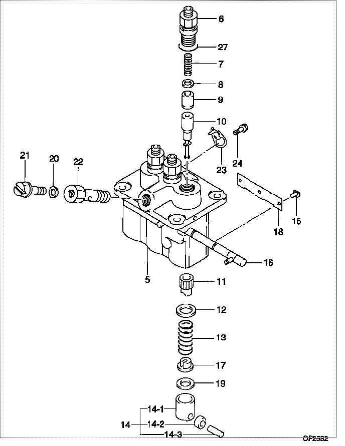
| 000. | [01] | 09450-06810 | PUMP ASSY, INJECTI | 31B6500050 |
| 005. | [01] | 09011-05110 | HOUSING SUB-ASSY, | 47X0106100 |
| 006. | [03] | 09013-10520 | HOLDER, DELIVERY V | |
| 007. | [03] | 09013-60540 | SPRING, DELIVERY V | |
| 008. | [03] | 09013-70130 | GASKET, DELIVERY V | |
| 009. | [03] | 09014-02610 | VALVE SUB-ASSY, IN | 47X0107700 |
| 010. | [03] | 09015-05550 | ELEMENT SUB-ASSY, | 47X0105400 |
| 011. | [03] | 09016-10210 | SLEEVE, PLUNGER CO | |
| 012. | [03] | 09016-30082 | SEAT, SPRING, UPR | MM501098 |
| 013. | [03] | 09016-40170 | SPRING, PUMP PLUNG | |
| 014. | [03] | 09017-00170 | TAPPET SUB-ASSY,IN | EZ01775027 |
| 014-001. | [03] | 09017-10021 | TAPPET, INJECTION | |
| 014-002. | [03] | 09217-60010 | ROLLER, FEED PUMP | 09217-60010 |
| 014-003. | [03] | 09017-60020 | PIN, INJECTION PUM | |
| 015. | [03] | 09018-30050 | PIN, INJECTION PUM | |
| 016. | [01] | 09021-00470 | RACK ASSY, CONTROL | |
| 017. | [03] | 09030-10060 | SEAT, SPRING, LWR | EZ0177514 |
| 018. | [01] | 09046-70040 | PLATE | |
| 019. | [3C] | 09031-10310 | PLATE, TAPPET ADJU | |
| 019. | [3C] | 09031-10300 | PLATE, TAPPET ADJU | |
| 019. | [3C] | 09031-10280 | PLATE, TAPPET ADJU | |
| 019. | [3C] | 09031-10170 | PLATE, TAPPET ADJU | FR51530028 |
| 019. | [3C] | 09031-10160 | PLATE, TAPPET ADJU | FR51530027 |
| 019. | [3C] | 09031-10140 | PLATE, TAPPET ADJU | 09031-10140 |
| 019. | [3C] | 09031-10130 | PLATE, TAPPET ADJU | 09031-10130 |
| 019. | [3C] | 09031-10120 | PLATE, TAPPET ADJU | 09031-10120 |
| 019. | [3C] | 09031-10110 | PLATE, TAPPET ADJU | 09031-10110 |
| 019. | [3C] | 09031-10010 | PLATE, TAPPET ADJU | 09031-10010 |
| 020. | [01] | 94901-81020 | WASHER, COPPER PLA | 94901-81020 |
| 020. | [01] | 09022-20080 | WASHER, FUEL PIPE | MM500114 |
| 021. | [01] | 09024-40180 | SCREW, AIR BLEEDER | |
| 022. | [01] | 09024-50210 | SCREW, HOLLOW | |
| 023. | [02] | 09006-80020 | PLATE, ADJUSTING | |
| 024. | [02] | 94904-80800 | BOLT, WASHER HEAD | MM514195 |
| 027. | [03] | 90802-20150 | O-RING | |
| 027. | [03] | 09013-90410 | O-RING | 47X0122700 |
Include in #3:
09450-06810
as PUMP ASSY, INJECTI
Cross reference number
| Part num | Firm num | Firm | Name |
| 09450-06810 | 31B6500050 | PUMP ASSY, INJECTI | |
| 31B6500050 | MITSUBISHI | PUMP ASSY, INJECTI |
Information:
1. Disconnect two fuel lines (1) from the fuel transfer pump. 2. Remove two bolts (3) and fuel transfer pump (2).Install Fuel Transfer Pump
1. Put fuel transfer pump (1) in position and install the two bolts that hold it to the fuel pump housing. 2. Connect two lines (2) to the fuel transfer pump.Disassemble Fuel Transfer Pump
start by:a) remove fuel transfer pump 1. Remove bolts (1) that hold transfer pump cover (2) to transfer pump body (5).2. Remove bolts and clamps (4) from the tachometer drive adapter. Remove tachometer drive adapter (3) from the cover. 3. Remove lip type seal (6) from the cover. Remove plug and O-ring seal (7), seat (8), spring (9) and valve (10) from the cover. 4. Remove nut (14) on end of shaft (11) and remove gear (17) and key (12) from the shaft. Remove O-ring seal (13) and the shaft from the body (5).5. Remove idler gear (15) from shaft (16).6. Remove the bearings and the two lip type seals from the body.7. Remove the check valve and shaft (16) from the body.Assemble Fuel Transfer Pump
1. Clean the openings (ports) for the fuel passage in body (3).2. Install shaft (1) and check valve (2) in the body with tooling (A).3. Install smaller bearing (4) in the body with tooling (B). Install the bearing until it is even with the machined surface of the body. 4. Install seal (5) in the body with tooling (C). Install the seal until it is .969 in. (24.6 mm) from the top surface of the body and with the lip toward bearing (4) as shown.5. Install seal (6) in body (3) with tooling (D). Install the seal until it is .563 in. (14.3 mm) from the top surface of the body and with the lip toward the top surface of body (3) as shown. 6. Install the large bearing in body (3) with tooling (E). Install the bearing even with the outside surface of the body. 7. Install the seal in cover (7) with tooling (C). Install the seal with the lip toward the inside of the cover and until it is .750 in. (19.1 mm) below the outside surface of the cover.8. Install the fuel bypass valve, the valve, spring, seal, O-ring seal and plug (14) in the cover. Tighten the plug to a torque of 27 3 lb.ft. (38 4 N m).9. Install shaft (9) in the body. Install gear (13) on the shaft to make an alignment with the gear on the shaft.10. Put 7M7260 Liquid Gasket Material on surface of cover (8). Install the cover on the body.
Do not let liquid gasket material enter the pump.
11. Install the six bolts that hold the cover (7) to the body. Install the O-ring seal to the body. The shaft must turn freely after the bolts that hold the cover in position are tightened.12. Install key (12) on the shaft. Install gear (8) on shaft and in alignment over the key. Install nut