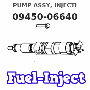
Information pump assy, injecti
Nozzle:
0935004660
Rating:
Compare Prices: .
As an associate, we earn commssions on qualifying purchases through the links below

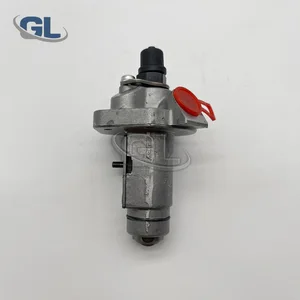
1pc Fuel Pump 1G141-51012 094500-6420 094500-6640, Compatible with Kubota OC95 Excavator Parts(094500-6640)
Adfghjk OE-Level Precision: Fuel Pump 1G141-51012 Compatible with Kubota OC95 Excavator, maintains ≤0.3% pressure variance, validated by ISO 16750-3 testing for seamless ECU integration. || Extreme Durability: JIS G5502 cast iron construction withstands 2,200 PSI, offering 50% longer lifespan in mining/construction environments. || Plug-and-Play Installation: Leak-proof quick-connect ports enable 1-hour replacement without modifications. || Fuel Efficiency Boost: Optimized plunger timing improves atomization by 12%, reducing emissions to meet EPA Tier 4 standards. || All-Climate Reliability: Operates flawlessly from -25℃ cold starts to 60℃ desert heat, ensuring uninterrupted performance.
Adfghjk OE-Level Precision: Fuel Pump 1G141-51012 Compatible with Kubota OC95 Excavator, maintains ≤0.3% pressure variance, validated by ISO 16750-3 testing for seamless ECU integration. || Extreme Durability: JIS G5502 cast iron construction withstands 2,200 PSI, offering 50% longer lifespan in mining/construction environments. || Plug-and-Play Installation: Leak-proof quick-connect ports enable 1-hour replacement without modifications. || Fuel Efficiency Boost: Optimized plunger timing improves atomization by 12%, reducing emissions to meet EPA Tier 4 standards. || All-Climate Reliability: Operates flawlessly from -25℃ cold starts to 60℃ desert heat, ensuring uninterrupted performance.

Fuel Pump Compatible With Kubota OC95 1G141-51012 094500-6420 094500-6640 SINOCMP 1PCS
CUHNB Model Compatibility: Designed to fit models with part numbers 1G141-51012, 094500-6420, and 094500-6640. || Efficient Performance: Provides reliable fuel delivery for engine in Kubota OC95. || Construction: Built to withstand demanding conditions and enhance overall operational efficiency. || Easy Installation: Simplifies the replacement process, saving time and effort during maintenance tasks. || Versatile Use: Suitable for various applications in farming-related, industrial, and construction machinery. || Cost-Effective Solution: Offers an economical option for fuel pump replacement without compromising functionality. || Reliable Fuel Supply: Ensures consistent fuel flow for engine performance and longevity.
CUHNB Model Compatibility: Designed to fit models with part numbers 1G141-51012, 094500-6420, and 094500-6640. || Efficient Performance: Provides reliable fuel delivery for engine in Kubota OC95. || Construction: Built to withstand demanding conditions and enhance overall operational efficiency. || Easy Installation: Simplifies the replacement process, saving time and effort during maintenance tasks. || Versatile Use: Suitable for various applications in farming-related, industrial, and construction machinery. || Cost-Effective Solution: Offers an economical option for fuel pump replacement without compromising functionality. || Reliable Fuel Supply: Ensures consistent fuel flow for engine performance and longevity.

Fuel Injection Pump 1G141-51012 1G141-51010 094500-6640 Fits for Kubota OC95 Engine
SXCCGMGQ Product Name:Fuel Injection Pump || Product Number:1G141-51012 1G141-51010 094500-6640 || Application:Fits for Kubota OC95 Engine || Easy installation: Standardized interface design, easy installation, no additional modification, users can easily complete replacement and maintenance. || Trustworthy: This product through strict quality testing, to provide reliable product quality and after-sales service, so that you use no worries.
SXCCGMGQ Product Name:Fuel Injection Pump || Product Number:1G141-51012 1G141-51010 094500-6640 || Application:Fits for Kubota OC95 Engine || Easy installation: Standardized interface design, easy installation, no additional modification, users can easily complete replacement and maintenance. || Trustworthy: This product through strict quality testing, to provide reliable product quality and after-sales service, so that you use no worries.
You can express buy:
USD 233.8
28-05-2025
28-05-2025
China Made New Fuel Injection Pump 1G141-51012 094500-6640 compatible for Kubota OC95
Components :
| 001. | PUMP ASSY, INJECTI | 09450-06640 |
Scheme ###:
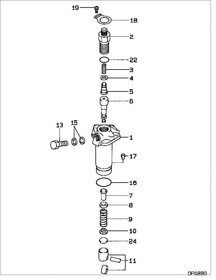
| 000. | [01] | 09450-06640 | PUMP ASSY, INJECTI | 1G141-51012 |
| 001. | [01] | 09011-05130 | HOUSING SUB-ASSY, | |
| 002. | [01] | 09013-10830 | HOLDER, DELIVERY V | 16241-51221 |
| 003. | [01] | 09013-60530 | SPRING, DELIVERY V | 16241-51231 |
| 004. | [01] | 09013-70130 | GASKET, DELIVERY V | 11420-51241 |
| 005. | [01] | 09014-01360 | VALVE SUB-ASSY, IN | 11420-51031 |
| 006. | [01] | 09015-04730 | ELEMENT SUB-ASSY, | |
| 007. | [01] | 09016-00140 | SLEEVE SUB-ASSY, C | 16241-51381 |
| 008. | [01] | 09016-30140 | SEAT, SPRING, UPR | 16241-51271 |
| 009. | [01] | 09016-40280 | SPRING, PUMP PLUNG | 16261-51281 |
| 010. | [01] | 09016-50170 | SEAT, SPRING, LWR | 16241-51291 |
| 011. | [01] | 09017-00220 | TAPPET SUB-ASSY,IN | 16241-51071 |
| 013. | [01] | 09024-50380 | SCREW, HOLLOW | 11420-51321 |
| 015. | [02] | 09025-10010 | WASHER, INJECTION | 15121-42671 |
| 016. | [01] | 94907-21430 | RING, SNAP | 11420-51261 |
| 017. | [01] | 09018-30120 | PIN, INJECTION PUM | 11420-51251 |
| 018. | [01] | 09023-00070 | PLATE SET, VALVE H | 16241-51301 |
| 019. | [01] | 94900-75390 | SCREW, W/WASHER | |
| 022. | [01] | 90801-10130 | O-RING | 16241-96761 |
| 022. | [01] | 09013-90400 | O-RING | |
| 024. | [1C] | 09031-10440 | PLATE, TAPPET ADJU | |
| 024. | [1C] | 09031-10430 | PLATE, TAPPET ADJU | |
| 024. | [1C] | 09031-10420 | PLATE, TAPPET ADJU | |
| 024. | [1C] | 09031-10410 | PLATE, TAPPET ADJU | |
| 024. | [1C] | 09031-10400 | PLATE, TAPPET ADJU | |
| 024. | [1C] | 09031-10390 | PLATE, TAPPET ADJU | |
| 024. | [1C] | 09031-10380 | PLATE, TAPPET ADJU | |
| 024. | [1C] | 09031-10370 | PLATE, TAPPET ADJU | |
| 024. | [1C] | 09031-10360 | PLATE, TAPPET ADJU | |
| 024. | [1C] | 09031-10350 | PLATE, TAPPET ADJU | |
| 024. | [1C] | 09031-10340 | PLATE, TAPPET ADJU | |
| 024. | [1C] | 09031-10330 | PLATE, TAPPET ADJU | |
| 024. | [1C] | 09031-10320 | PLATE, TAPPET ADJU | 16241-51491 |
| 024. | [1C] | 09031-10450 | PLATE, TAPPET ADJU |
Include in #3:
09450-06640
as PUMP ASSY, INJECTI
Cross reference number
| Part num | Firm num | Firm | Name |
| 09450-06640 | 1G141-5101 | PUMP ASSY, INJECTI | |
| 1G141-51012 | KUBOTA | PUMP ASSY, INJECTI |
Information:
Before any service work is done on the fuel system, the outer surface of the injection pump housing must be clean.
1. Remove the plug from location (1). Install tool (A) in the hole with the large diameter end without the taper down. Move the governor control to the "ON" position until the rack stops against tool (A). The racks are now in center (zero) position.2. Disconnect lines (2) from the fuel injection pumps. Remove the washers. Put caps on all fuel openings. 3. Remove bushings (3) with tooling (B). 4. Install tooling (C). Hold the fuel racks in the center (zero) position and carefully remove the fuel injection pump.
When injection pumps, spacers and lifters are removed from the injection pump housing, keep the parts of each pump together so they can be installed back in their original location.
5. Remove spacers (4) from the fuel injection pump housing.
Be careful when the injection pumps are disassembled. Do not cause damage to the surface on the plunger. The plunger and barrel for each pump are made as a set. Do not put the plunger of one pump in the barrel of another pump. If one part has wear, install a complete new pump assembly. Be careful when the plunger is put into the bore of the barrel.
Do not remove gear segment (15) from plunger (10).
6. Remove plunger (10), washer (14) and spring (9) from barrel (8).7. Remove ring (12) from barrel (8) and bonnet (11).8. Remove spring (6), collar (7) and check valve assembly (13) from bonnet (11). Do not disassemble check valve assembly (13).9. Keep seal (5) with the bonnet for use at assembly.Install Fuel Injection Pumps
Make sure the fuel racks are in the center (ZERO) position before the fuel injection pumps are installed.1. Put diesel fuel on all parts to be assembled. 2. Put spring (2), collar (3) and check valve assembly (9) in position in the bonnet.
Do not slide barrel (4) against the check valve assembly when it is assembled. Scratches on the check valve can cause it to leak.
3. Put the bonnet assembly (7) and barrel (4) in position and install ring (8).4. Install spring (5), washer (10) and plunger assembly (6). 5. Put spacer (12) in position in the pump housing bore. Make sure the correct spacer is with each pump. The lobe on the cam must be at its lowest position for easy installation of the fuel injection pumps.6. Hold the fuel racks in the center (ZERO) position when the fuel pumps are installed. Put the space in gear segment (11) in alignment with the groove in barrel (4). 7. Put the injection pump straight down into the housing bore so the space in the gear segment is in alignment with pin (13) and the groove in the barrel is in alignment with dowel (14). Use tool (B) to install the pump. 8. Install seal (1) and bushing (15) in the pump housing bore. If the pump is in the correct position, bushing (15) will