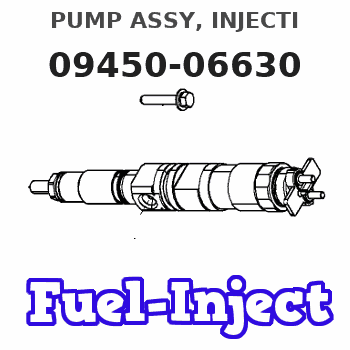
Information pump assy, injecti
Nozzle:
0935004660
Rating:
Compare Prices: .
As an associate, we earn commssions on qualifying purchases through the links below

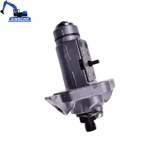
1G131-51012 094500-6630 Fuel Injection Pump Compatible for Kubota OC60 KC70 Engine
JPSMZSC Product Name:Fuel Injection Pump || Part number:1G131-51012 094500-6630 || Application:Compatible for Kubota OC60 KC70 Engine || Note: Please confirm that the product shown in the part number is what you need. If you cannot confirm, you can leave us a message and provide your engine serial number and nameplate. || Tip: We mainly deal in all parts of the construction machinery series. Our product has stable performance, fast response, high reliability, and easy installation. High quality, most guaranteed. If you have any other requirements, please contact us.
JPSMZSC Product Name:Fuel Injection Pump || Part number:1G131-51012 094500-6630 || Application:Compatible for Kubota OC60 KC70 Engine || Note: Please confirm that the product shown in the part number is what you need. If you cannot confirm, you can leave us a message and provide your engine serial number and nameplate. || Tip: We mainly deal in all parts of the construction machinery series. Our product has stable performance, fast response, high reliability, and easy installation. High quality, most guaranteed. If you have any other requirements, please contact us.

Fuel Pump 1G131-51012 094500-6630 094500-6410 Compatible With Kubota OC60 KC70 Accessories
DGTYBHR The fuel pump sucks the fuel out of the tank, pressurizes it and sends it to the fuel system of the engine, and the engine gets enough fuel supply. || The pump body is the main body of the fuel pump, which contains various moving parts. || It is composed of pump body, drive mechanism, oil port, safety valve and so on. || When installing the fuel pump, ensure that the installation position is correct and the connection is firm. || Note that the import and export direction of the fuel pump cannot be reversed, otherwise it cannot be normally transmitted
DGTYBHR The fuel pump sucks the fuel out of the tank, pressurizes it and sends it to the fuel system of the engine, and the engine gets enough fuel supply. || The pump body is the main body of the fuel pump, which contains various moving parts. || It is composed of pump body, drive mechanism, oil port, safety valve and so on. || When installing the fuel pump, ensure that the installation position is correct and the connection is firm. || Note that the import and export direction of the fuel pump cannot be reversed, otherwise it cannot be normally transmitted

You can express buy:
USD 446.36
05-05-2025
05-05-2025
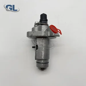
Fuel Pump 1G131-51012 094500-6630 094500-6410 For Kubota OC60 KC70 High Quality Accessories
USD 234.3
27-05-2025
27-05-2025
China Made New Fuel Injection Pump 1G131-51012 094500-6630 compatible for Kubota OC60/KC70
Components :
| 001. | PUMP ASSY, INJECTI | 09450-06630 |
Scheme ###:
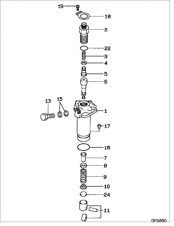
| 000. | [01] | 09450-06630 | PUMP ASSY, INJECTI | 1G131-51012 |
| 001. | [01] | 09011-05130 | HOUSING SUB-ASSY, | |
| 002. | [01] | 09013-10830 | HOLDER, DELIVERY V | 16241-51221 |
| 003. | [01] | 09013-60530 | SPRING, DELIVERY V | 16241-51231 |
| 004. | [01] | 09013-70130 | GASKET, DELIVERY V | 11420-51241 |
| 005. | [01] | 09014-01360 | VALVE SUB-ASSY, IN | 11420-51031 |
| 006. | [01] | 09015-04630 | ELEMENT SUB-ASSY, | |
| 007. | [01] | 09016-00140 | SLEEVE SUB-ASSY, C | 16241-51381 |
| 008. | [01] | 09016-30140 | SEAT, SPRING, UPR | 16241-51271 |
| 009. | [01] | 09016-40280 | SPRING, PUMP PLUNG | 16261-51281 |
| 010. | [01] | 09016-50170 | SEAT, SPRING, LWR | 16241-51291 |
| 011. | [01] | 09017-00220 | TAPPET SUB-ASSY,IN | 16241-51071 |
| 013. | [01] | 09024-50380 | SCREW, HOLLOW | 11420-51321 |
| 015. | [02] | 09025-10010 | WASHER, INJECTION | 15121-42671 |
| 016. | [01] | 94907-21430 | RING, SNAP | 11420-51261 |
| 017. | [01] | 09018-30120 | PIN, INJECTION PUM | 11420-51251 |
| 018. | [01] | 09023-00070 | PLATE SET, VALVE H | 16241-51301 |
| 019. | [01] | 94900-75390 | SCREW, W/WASHER | |
| 022. | [01] | 90801-10130 | O-RING | 16241-96761 |
| 022. | [01] | 09013-90400 | O-RING | |
| 024. | [1C] | 09031-10440 | PLATE, TAPPET ADJU | |
| 024. | [1C] | 09031-10430 | PLATE, TAPPET ADJU | |
| 024. | [1C] | 09031-10420 | PLATE, TAPPET ADJU | |
| 024. | [1C] | 09031-10410 | PLATE, TAPPET ADJU | |
| 024. | [1C] | 09031-10400 | PLATE, TAPPET ADJU | |
| 024. | [1C] | 09031-10390 | PLATE, TAPPET ADJU | |
| 024. | [1C] | 09031-10380 | PLATE, TAPPET ADJU | |
| 024. | [1C] | 09031-10370 | PLATE, TAPPET ADJU | |
| 024. | [1C] | 09031-10360 | PLATE, TAPPET ADJU | |
| 024. | [1C] | 09031-10350 | PLATE, TAPPET ADJU | |
| 024. | [1C] | 09031-10340 | PLATE, TAPPET ADJU | |
| 024. | [1C] | 09031-10330 | PLATE, TAPPET ADJU | |
| 024. | [1C] | 09031-10320 | PLATE, TAPPET ADJU | 16241-51491 |
| 024. | [1C] | 09031-10450 | PLATE, TAPPET ADJU |
Include in #3:
09450-06630
as PUMP ASSY, INJECTI
Cross reference number
| Part num | Firm num | Firm | Name |
| 09450-06630 | 1G131-5101 | PUMP ASSY, INJECTI | |
| 1G131-51012 | KUBOTA | PUMP ASSY, INJECTI |
Information:
1. Remove strainer (2) from governor cover (1). 2. Bend the locks back and remove four bolts (6). Remove levers (4) and (5).3. Remove shaft (3) and the washer from the governor cover. 4. Remove two bearings (7) and two seals (8) from the governor cover with tooling (A). 5. Remove insulator (9) from governor cover (1). 6. Put a mark on the high idle screw (10) and make a note of each turn until the idle screw is removed from governor housing (13). This is done to get the approximate setting for assembly purposes. Remove the O-ring seal from the idle screw.
Do not mix the sequence of insulators, shims, spacers, contact, bar and spring. For more information see FUEL SETTING INFORMATION Fiche SBFY1106. The sequence of these parts can be different between engines. Bend lock (11) down and remove the two bolts. Remove torque spring group (12). Remove lock, retainer, insulator, spacer, contact, spring, spacer, shim, bar and insulator.
8. Bend the lock down and remove bolt (15) from control lever (14). Remove shaft (16) and control lever (14) from the governor housing. 9. Remove band assembly (17) from control lever (14).
Care must be taken when pin (18) is removed. The spring and plunger behind pin (18) are under spring force.
10. Remove pin (18), spring and plunger from control lever (14). 11. Remove bearings (19) and two seals (20) from governor housing (13). 12. Remove seat (21), spring washer (22), flat washer (24), spring washer (23) and spring (25). 13. Remove washer (27) from governor bolt (26).14. Remove ring (28) from seat (29). 15. Remove dowel (30) from seat (29). Remove seat (29) and governor bolt (26) as a unit. Remove bolt (26) from seat (29). 16. Remove washer (31), spring (32), washer (33) and sleeve (34) from the servo piston valve. 17. Remove ring (38), large race (37), bearing (35) and small race (36) from sleeve (34). 18. Remove lock (40) from flyweight assembly (39). Remove flyweight assembly (40). 19. Bend the locks from bolts (41) and remove bolts (41).20. Remove bracket (42) and the servo piston assembly as a unit. 21. Remove piston (44) from pin (43). Remove pin (43) from bracket (42). 22. Remove sleeve (45) and valve (46) from piston (44). Remove O-ring seal (47) from sleeve (45). 23. Remove shaft (48) from bracket (42) with a hammer and punch.24. Remove lever (49) from bracket (42). 25. Hit (tap) lightly on cylinder (50) to remove it from the governor plate. 26. Remove O-ring seals (51) from cylinder (50). 27. Remove spiral ring (53), and then remove dowel (52) behind the spiral ring. 28. Remove drive assembly (54) and stop (55) from drive gear (56). 29. Turn the governor plate over and remove snap ring (57) from drive gear (56) with tool (B).30. Remove drive gear (56) from the governor plate. 31. If a replacement is needed, remove dowels (59), (60) and (61).32. Remove bearing (58) from the governor plate with tooling (A).Assemble Governor
1. If