Information pump assy, injecti
Rating:
Components :
| 001. | PUMP ASSY, INJECTI | 09450-06491 |
| 001. | PUMP ASSY, INJECTI | 09450-06491 |
Scheme ###:
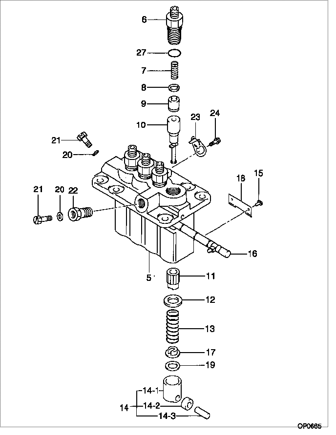
| 000. | [01] | 09450-06490 | PUMP ASSY, INJECTI | 31A6511050 |
| 000. | [01] | 09450-06491 | PUMP ASSY, INJECTI | 31A6521050 |
| 005. | [01] | 09011-05070 | HOUSING SUB-ASSY, | 47X0104200 |
| 006. | [04] | 09013-10520 | HOLDER, DELIVERY V | |
| 007. | [04] | 09013-60640 | SPRING, DELIVERY V | |
| 008. | [04] | 09013-70130 | GASKET, DELIVERY V | |
| 009. | [04] | 09014-00620 | VALVE SUB-ASSY, IN | 47X0105800 |
| 010. | [04] | 09015-02400 | ELEMENT SUB-ASSY, | |
| 011. | [04] | 09016-10210 | SLEEVE, PLUNGER CO | |
| 012. | [04] | 09016-30082 | SEAT, SPRING, UPR | MM501098 |
| 013. | [04] | 09016-40170 | SPRING, PUMP PLUNG | |
| 014. | [04] | 09017-00170 | TAPPET SUB-ASSY,IN | EZ01775027 |
| 014-001. | [04] | 09017-10021 | TAPPET, INJECTION | |
| 014-002. | [04] | 09217-60010 | ROLLER, FEED PUMP | 09217-60010 |
| 014-003. | [04] | 09017-60020 | PIN, INJECTION PUM | |
| 015. | [04] | 09018-30050 | PIN, INJECTION PUM | |
| 016. | [01] | 09021-00440 | RACK ASSY, CONTROL | |
| 017. | [04] | 09030-10060 | SEAT, SPRING, LWR | EZ0177514 |
| 018. | [02] | 09046-70030 | PLATE | |
| 019. | [4C] | 09031-10310 | PLATE, TAPPET ADJU | |
| 019. | [4C] | 09031-10300 | PLATE, TAPPET ADJU | |
| 019. | [4C] | 09031-10280 | PLATE, TAPPET ADJU | |
| 019. | [4C] | 09031-10170 | PLATE, TAPPET ADJU | FR51530028 |
| 019. | [4C] | 09031-10160 | PLATE, TAPPET ADJU | FR51530027 |
| 019. | [4C] | 09031-10140 | PLATE, TAPPET ADJU | 09031-10140 |
| 019. | [4C] | 09031-10130 | PLATE, TAPPET ADJU | 09031-10130 |
| 019. | [4C] | 09031-10120 | PLATE, TAPPET ADJU | 09031-10120 |
| 019. | [4C] | 09031-10110 | PLATE, TAPPET ADJU | 09031-10110 |
| 019. | [4C] | 09031-10010 | PLATE, TAPPET ADJU | 09031-10010 |
| 020. | [02] | 94901-81020 | WASHER, COPPER PLA | 94901-81020 |
| 020. | [02] | 09022-20080 | WASHER, FUEL PIPE | MM500114 |
| 020. | [01] | 09022-20080 | WASHER, FUEL PIPE | MM500114 |
| 021. | [01] | 09024-40180 | SCREW, AIR BLEEDER | |
| 021. | [02] | 09024-40180 | SCREW, AIR BLEEDER | |
| 022. | [01] | 94918-00310 | SCREW, HOLLOW | 85265-00078 |
| 022. | [01] | 94918-00510 | SCREW, HOLLOW | MM500083 |
| 023. | [03] | 09006-80020 | PLATE, ADJUSTING | |
| 024. | [03] | 94904-80800 | BOLT, WASHER HEAD | MM514195 |
| 027. | [04] | 90802-20150 | O-RING |
Include in #3:
09450-06491
as PUMP ASSY, INJECTI
Cross reference number
| Part num | Firm num | Firm | Name |
| 09450-06491 | 31A6521050 | PUMP ASSY, INJECTI |
Information:
Cylinder, Valve And Injection Pump LocationBore ... 5.40 in.(137.2 mm)Stroke ... 6.00 in.(152.4 mm)Number and Arrangement of Cylinders ... V-8Firing Order (Injection Sequence) ... 1,8,4,3,6,5,7,2Rotation of Crankshaft (when seen from flywheel end)...counterclockwiseRotation of Fuel Pump Camshaft (when seen from pump drive end) ... counterclockwise Front end of engine is opposite to flywheel end.Left side and right side of engine are as seen from flywheel end.No. 1 cylinder is the front cylinder on the left side.No. 2 cylinder is the front cylinder on the right side.Fuel System
Fuel System Schematic
(1) Fuel inlet line for the injection pump housing. (2) Damper. (3) Adapter with orifice. (4) Injection pump housing. (5) Fuel return line. (6) Fuel tank. (7) Fuel supply line. (8) Primary fuel filter. (9) Fuel transfer pump. (10) Fuel priming pump. (11) Main fuel filter.This engine has a pressure type fuel system. There is one injection pump and injection nozzle for each cylinder. The injection pumps are in the pump housing (4) on top front of the engine. The injection nozzles are in the precombustion chambers or adapters (for engines with direct injection) under the valve covers.The transfer pump (9) pulls fuel from the fuel tanks (6) through the primary filter (8) and sends it through the priming pump (10), main filter (11) and to the manifold of the injection pump housing. The fuel in the manifold of the injection pump housing goes to the injection pumps. The injection pumps are in time with the engine and send fuel to the injection nozzles under high pressure.Some of the fuel in the manifold is constantly sent back through the return line (5) to the fuel tank to remove air from the system. On the outlet elbow of the injection pump there is a damper (2) to reduce shock loads, and a restriction orifice (3) to keep fuel pressure high and to control the amount of fuel that goes back to the fuel tank.
Location Of Fuel System Components
(1) Fuel inlet line for the injection pump housing. (2) Damper. (4) Injection pump housing. (9) Fuel transfer pump. (10) Fuel priming pump. (11) Main fuel filter. (12) Nut for a fuel injection line at the injection pump. (13) Fuel manifold across the injection pump housing. (14) Adapter through the valve cover base.The fuel priming pump (10) is used to fill the system with fuel and to remove air from the fuel filter, fuel lines and components.The transfer pump has a bypass valve and a check valve. The bypass valve (lower side) controls the maximum pressure of the fuel. The extra fuel goes to the inlet of the pump. The check valve allows the fuel from the tank to go around the transfer pump gears when the priming pump is used.Fuel Injection Pump
The rotation of the cams on the camshaft (12) cause lifters (9) and pump plungers (5) to move up and down. The stroke of each pump plunger is always the same. The force of springs (6) hold lifters (9) against the cams of