Information pump assy, injecti
Nozzle:
0935004330
Rating:
Components :
| 001. | PUMP ASSY, INJECTI | 09450-06200 |
Scheme ###:
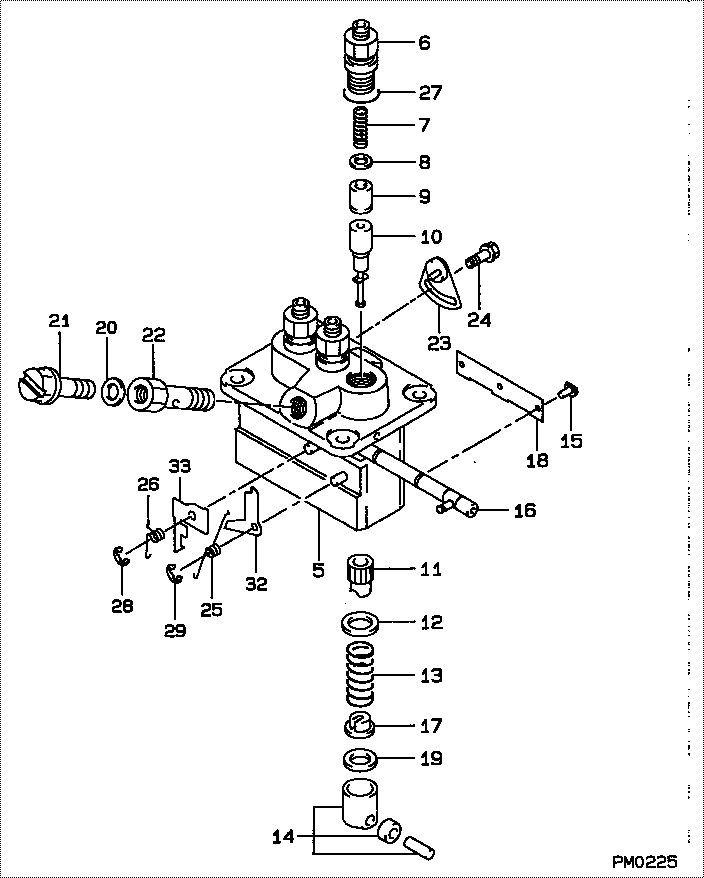
| 000. | [01] | 09450-06200 | PUMP ASSY, INJECTI | 30A6504500 |
| 005. | [01] | 09011-03480 | HOUSING SUB-ASSY, | |
| 005. | [01] | 09011-02590 | HOUSING SUB-ASSY, | |
| 006. | [03] | 09013-10720 | HOLDER, DELIVERY V | |
| 007. | [03] | 09013-60480 | SPRING, DELIVERY V | |
| 008. | [03] | 09013-70130 | GASKET, DELIVERY V | |
| 009. | [03] | 09014-01880 | VALVE SUB-ASSY, IN | |
| 010. | [03] | 09015-04640 | ELEMENT SUB-ASSY, | |
| 011. | [03] | 09016-10210 | SLEEVE, PLUNGER CO | |
| 012. | [03] | 09016-30082 | SEAT, SPRING, UPR | MM501098 |
| 013. | [03] | 09016-40170 | SPRING, PUMP PLUNG | |
| 014. | [03] | 09017-00170 | TAPPET SUB-ASSY,IN | EZ01775027 |
| 014-001. | [03] | 09017-10021 | TAPPET, INJECTION | |
| 014-002. | [03] | 09217-60010 | ROLLER, FEED PUMP | 09217-60010 |
| 014-003. | [03] | 09017-60020 | PIN, INJECTION PUM | |
| 015. | [03] | 09018-30050 | PIN, INJECTION PUM | |
| 016. | [01] | 09021-00470 | RACK ASSY, CONTROL | |
| 017. | [03] | 09030-10060 | SEAT, SPRING, LWR | EZ0177514 |
| 018. | [01] | 09046-70040 | PLATE | |
| 019. | [3C] | 09031-10310 | PLATE, TAPPET ADJU | |
| 019. | [3C] | 09031-10300 | PLATE, TAPPET ADJU | |
| 019. | [3C] | 09031-10280 | PLATE, TAPPET ADJU | |
| 019. | [3C] | 09031-10170 | PLATE, TAPPET ADJU | FR51530028 |
| 019. | [3C] | 09031-10160 | PLATE, TAPPET ADJU | FR51530027 |
| 019. | [3C] | 09031-10140 | PLATE, TAPPET ADJU | 09031-10140 |
| 019. | [3C] | 09031-10130 | PLATE, TAPPET ADJU | 09031-10130 |
| 019. | [3C] | 09031-10120 | PLATE, TAPPET ADJU | 09031-10120 |
| 019. | [3C] | 09031-10110 | PLATE, TAPPET ADJU | 09031-10110 |
| 019. | [3C] | 09031-10010 | PLATE, TAPPET ADJU | 09031-10010 |
| 020. | [01] | 09022-20080 | WASHER, FUEL PIPE | MM500114 |
| 020. | [01] | 94901-81020 | WASHER, COPPER PLA | 94901-81020 |
| 021. | [01] | 09024-40180 | SCREW, AIR BLEEDER | |
| 022. | [01] | 09024-50210 | SCREW, HOLLOW | |
| 023. | [02] | 09006-80020 | PLATE, ADJUSTING | |
| 024. | [02] | 94904-80800 | BOLT, WASHER HEAD | MM514195 |
| 025. | [01] | 09055-40470 | SPRING, DIAPHRAGM | |
| 026. | [01] | 09055-40280 | SPRING, DIAPHRAGM | |
| 027. | [03] | 90802-20150 | O-RING | |
| 028. | [01] | 09089-40020 | E-RING | 09089-40020 |
| 029. | [01] | 09089-40010 | E-RING | 09089-40010 |
| 032. | [1C] | 09021-95370 | STOPPER | |
| 032. | [1C] | 09021-95360 | STOPPER | MM501747 |
| 032. | [1C] | 09021-93120 | STOPPER | |
| 032. | [1C] | 09021-93110 | STOPPER | |
| 032. | [1C] | 09021-93100 | STOPPER | |
| 032. | [1C] | 09021-93090 | STOPPER | |
| 032. | [1C] | 09021-93080 | STOPPER | |
| 033. | [1C] | 09021-93840 | STOPPER | |
| 033. | [1C] | 09021-93850 | STOPPER | |
| 033. | [1C] | 09021-93860 | STOPPER | |
| 033. | [1C] | 09021-95760 | STOPPER | |
| 033. | [1C] | 09021-95770 | STOPPER | MM514006 |
| 033. | [1C] | 09021-95780 | STOPPER | MM514007 |
| 033. | [1C] | 09021-93830 | STOPPER | |
| 033. | [1C] | 09021-93820 | STOPPER | |
| 033. | [1C] | 09021-93810 | STOPPER | |
| 033. | [1C] | 09021-93800 | STOPPER | |
| 033. | [1C] | 09021-93790 | STOPPER | |
| 033. | [1C] | 09021-93780 | STOPPER | |
| 033. | [1C] | 09021-93770 | STOPPER | |
| 033. | [1C] | 09021-93760 | STOPPER | |
| 033. | [1C] | 09021-95790 | STOPPER | MM514008 |
Include in #3:
09450-06200
as PUMP ASSY, INJECTI
Cross reference number
| Part num | Firm num | Firm | Name |
| 09450-06200 | 30A6504500 | PUMP ASSY, INJECTI | |
| 30A6504500 | MITSUBISHI | PUMP ASSY, INJECTI |
Information:
Do not operate or work on this product unless you have read and understood the instruction and warnings in the relevant Operation and Maintenance Manuals and relevant service literature. Failure to follow the instructions or heed the warnings could result in injury or death. Proper care is your responsibility.
The following changes are now available for the products within the listed serial numbers.New injector coolant tank assembly is now available for the machines listed above. The new coolant tank assembly provides better reliability against coolant leakage.Required Parts
Table 1
Required Parts
Item Qty New Part Number Part Name Former Part Number(1)
1 1 573-8722 Coolant Tank As 469-9108
2 1 586-9617 Bracket As 491-3429
3 1 570-0813 Hose 474-9783
(1) The former part number listed is for reference only and may differ.Refer to "Replacement Procedure" for the procedure to install a new coolant tank assembly (1).Replacement Procedure
Illustration 1 g06464028
(A) Hood
Illustration 2 g06464029
(B) Tank assembly
Remove hood (A) to gain access to tank assembly (B).
Illustration 3 g06464030
(B) Tank assembly
(C) Hose
(D) Clamp
Disconnect hose (C) from tank assembly (B) by removing clamp (D).
Illustration 4 g06464533
(E) Special connector
(F) Hose assembly
(H) Clips
Illustration 5 g06464539
(G) Bolts
Disconnect special connector (E). Remove tank assembly with hose assembly (F) by removing bolts (G). Remove clips (H) and special connector (E) from hose assembly (F).
Illustration 6 g06464548
(K) Bracket
(L) Bolts
Remove bracket (K) by removing bolts (L).
Illustration 7 g06464563
(1) 573-8722 Coolant Tank As
(3) 570-0813 Hose
(E) Special connector
(H) Clips
Illustration 8 g06464617
(D1) 27 degrees
(D2) 15 mm (0.6 inch)
(D3) 10 mm (0.4 inch)
Sub-assemble new tank assembly (1), hose (3), and special connector (E) with clips (H).Note: Align hose (3) and special connector (E) at the correct angle. Refer to Illustration 7 and 8 for proper alignment.
Illustration 9 g06464631
(2) 586-9617 Bracket As
(L) Bolts
Install new bracket assembly (2) with bolts (L). Torque bolts (L) to 12 3 N m (106.2 26.6 lb in)