Information pump assy, injecti
Rating:
Components :
| 001. | PUMP ASSY, INJECTI | 09450-05190 |
Scheme ###:
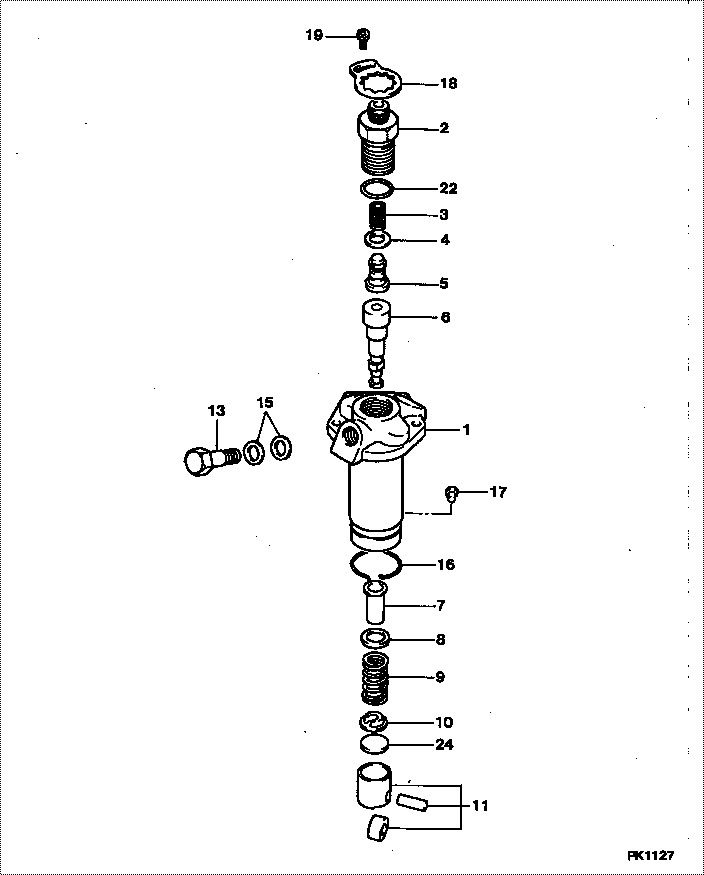
| 000. | [01] | 09450-05190 | PUMP ASSY, INJECTI | 11550-51011 |
| 001. | [01] | 09011-04270 | HOUSING SUB-ASSY, | 11420-51081 |
| 002. | [01] | 09013-00390 | HOLDER SUB-ASSY, D | 16261-51221 |
| 003. | [01] | 09013-60530 | SPRING, DELIVERY V | 16241-51231 |
| 004. | [01] | 09013-70130 | GASKET, DELIVERY V | 11420-51241 |
| 005. | [01] | 09014-01360 | VALVE SUB-ASSY, IN | 11420-51031 |
| 006. | [01] | 09015-04720 | ELEMENT SUB-ASSY, | |
| 007. | [01] | 09016-00140 | SLEEVE SUB-ASSY, C | 16241-51381 |
| 008. | [01] | 09016-30140 | SEAT, SPRING, UPR | 16241-51271 |
| 009. | [01] | 09016-40280 | SPRING, PUMP PLUNG | 16261-51281 |
| 010. | [01] | 09016-50170 | SEAT, SPRING, LWR | 16241-51291 |
| 011. | [01] | 09017-00220 | TAPPET SUB-ASSY,IN | 16241-51071 |
| 013. | [01] | 09024-50380 | SCREW, HOLLOW | 11420-51321 |
| 015. | [02] | 09025-10010 | WASHER, INJECTION | 15121-42671 |
| 016. | [01] | 94907-21430 | RING, SNAP | 11420-51261 |
| 017. | [01] | 09018-30120 | PIN, INJECTION PUM | 11420-51251 |
| 018. | [01] | 09023-00070 | PLATE SET, VALVE H | 16241-51301 |
| 019. | [01] | 94900-75390 | SCREW, W/WASHER | |
| 019. | [01] | 91370-05101 | SCREW, W/WASHER | 16241-91431 |
| 022. | [01] | 90801-10130 | O-RING | 16241-96761 |
| 022. | [01] | 09013-90400 | O-RING | |
| 024. | [1C] | 09031-10440 | PLATE, TAPPET ADJU | |
| 024. | [1C] | 09031-10430 | PLATE, TAPPET ADJU | |
| 024. | [1C] | 09031-10420 | PLATE, TAPPET ADJU | |
| 024. | [1C] | 09031-10410 | PLATE, TAPPET ADJU | |
| 024. | [1C] | 09031-10400 | PLATE, TAPPET ADJU | |
| 024. | [1C] | 09031-10390 | PLATE, TAPPET ADJU | |
| 024. | [1C] | 09031-10380 | PLATE, TAPPET ADJU | |
| 024. | [1C] | 09031-10370 | PLATE, TAPPET ADJU | |
| 024. | [1C] | 09031-10360 | PLATE, TAPPET ADJU | |
| 024. | [1C] | 09031-10350 | PLATE, TAPPET ADJU | |
| 024. | [1C] | 09031-10340 | PLATE, TAPPET ADJU | |
| 024. | [1C] | 09031-10330 | PLATE, TAPPET ADJU | |
| 024. | [1C] | 09031-10320 | PLATE, TAPPET ADJU | 16241-51491 |
| 024. | [1C] | 09031-10450 | PLATE, TAPPET ADJU |
Include in #3:
09450-05190
as PUMP ASSY, INJECTI
Cross reference number
| Part num | Firm num | Firm | Name |
| 09450-05190 | 11550-5101 | PUMP ASSY, INJECTI | |
| 11550-51011 | KUBOTA | PUMP ASSY, INJECTI |
Information:
Introduction
Do not perform any procedure in this Special Instruction until you have read the information and you understand the information.If the crankshaft and/or flywheel are replaced or set, it is necessary to calibrate the injection timing. The following steps show how to calculate/determine the new injection timing by measuring angular deviation between the crankshaft TDC and Crank Position sensor detected TDC.Note: Once completed the engine ecm must be reprogrammed with the new injection timing value.Follow all Steps below.Required Tools
Dial Gauge
Tri - Square
483-5054 C2.4 Injection Top Correction JigProcedure
Illustration 1 g06220154
(1) Rocker Arm
(2) Valve Spring
While the engine is out of the machine, remove the valve cover and rocker arm (1).
Illustration 2 g06220155
(3) Dial Gauge
(4) O-ring
(5) Exhaust Valve
Align the #4 piston with TDC and remove the valve spring (2) of the #4 cylinder. Insert an O-ring (4) to prevent the exhaust valve (5) from falling into the cylinder and position the dial gauge (3) at the tip of the valve.
While turning the flywheel counterclockwise, stop the flywheel when you see the largest needle movement on the gauge. Which indicates TDC.
Illustration 3 g06220158
(6) Tri - Square
Illustration 4 g06220159
(7) Mark for TDC
(8) Reference Line
While the flywheel is in this position, set the tri-square (6) as indicated in the Illustration 3 and place a TDC mark (7) on the reference line (8) and flywheel on the engine body side. In the case the flywheel is turned too far, return flywheel by turning clockwise and start over.
Illustration 5 g06220162
(9) Area where there is no pulsar hole
(10) Flywheel
(11) Flywheel Housing
(12) Crank Position Sensor Mounting Hole
(13) Reference Pulsar Hole 20th
To confirm that the crank position sensor is at the TDC detection position: Align the reference 20th pulsar hole (13) from the area where there is no pulsar hole (9) on the outer circumference of the flywheel (10) with the crank position sensor mounting hole (12) on the flywheel housing (12).
Illustration 6 g06220413
(14) Injection Top Correction Jig
Insert the injection tooling jig (14) into the crank position sensor mounting hole and align the center of the handle and pulsar.
Illustration 7 g06220442
(6) Tri - Square
(8) Reference Line
Illustration 8 g06220454
(15) Mark of Crank Position Sensor TDC Detection Position
This position is the crank position sensor TDC detection position, so position the tri - square (6) on the reference line (8) and make a crank position sensor TDC detection position mark (15) on the flywheel.
Illustration 9 g06220464
(7) Mark for TDC
(15) Mark of Crank Position Sensor TDC Detection Position
(16) Correction Amount (mm)
The difference (16) between the TDC mark (7) and the crank position sensor TDC detection mark (15) is the correction amount for fuel injection timing.To calculate the correction value: 1 mm = (360°) / (Flywheel Diameter x π)(For Example) FD = 300 mm → 1 mm = 0.38°Correction amount (CA) = 0.38 X A (mm)
If the crank position sensor top dead center detection position is in front of TDC, enter a negative value when registering injection correction value.
If the crank position sensor top dead center detection position is in back of top dead center, enter a positive value when registering injection correction