Information pump assy, injecti
Nozzle:
0935001660
Rating:
Components :
| 001. | PUMP ASSY, INJECTI | 09450-05040 |
Scheme ###:
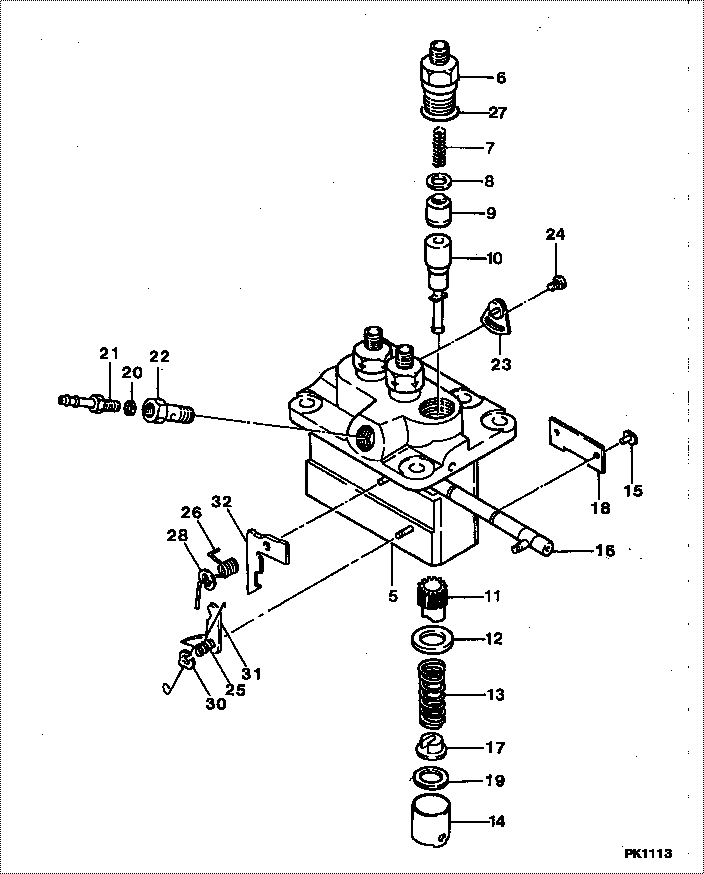
| 000. | [01] | 09450-05040 | PUMP ASSY, INJECTI | MM438105 |
| 005. | [01] | 09011-02590 | HOUSING SUB-ASSY, | MM501312 |
| 006. | [03] | 09013-10520 | HOLDER, DELIVERY V | MM501507 |
| 007. | [03] | 09013-60540 | SPRING, DELIVERY V | MM501161 |
| 008. | [03] | 09013-70061 | GASKET, DELIVERY V | P720-16141 |
| 008. | [03] | 09013-70130 | GASKET, DELIVERY V | MM501856 |
| 009. | [03] | 09014-00800 | VALVE SUB-ASSY, IN | MM501076 |
| 010. | [03] | 09015-04150 | ELEMENT SUB-ASSY, | |
| 011. | [03] | 09016-10210 | SLEEVE, PLUNGER CO | MM500229 |
| 012. | [03] | 09016-30082 | SEAT, SPRING, UPR | MM501098 |
| 013. | [03] | 09016-40170 | SPRING, PUMP PLUNG | MM500360 |
| 014. | [03] | 09017-00170 | TAPPET SUB-ASSY,IN | MM500230 |
| 014-001. | [03] | 09017-10021 | TAPPET, INJECTION | |
| 014-002. | [03] | 09217-60010 | ROLLER, FEED PUMP | ME702227 |
| 014-003. | [03] | 09017-60020 | PIN, INJECTION PUM | P720-1429 |
| 015. | [03] | 09018-30050 | PIN, INJECTION PUM | MM500231 |
| 016. | [01] | 09021-00470 | RACK ASSY, CONTROL | MM501311 |
| 017. | [03] | 09030-10060 | SEAT, SPRING, LWR | MM500316 |
| 018. | [01] | 09046-70040 | PLATE | MM501162 |
| 019. | [3C] | 09031-10310 | PLATE, TAPPET ADJU | MM501365 |
| 019. | [3C] | 09031-10300 | PLATE, TAPPET ADJU | MM501364 |
| 019. | [3C] | 09031-10280 | PLATE, TAPPET ADJU | MM501246 |
| 019. | [3C] | 09031-10170 | PLATE, TAPPET ADJU | P760-15160 |
| 019. | [3C] | 09031-10160 | PLATE, TAPPET ADJU | MM500314 |
| 019. | [3C] | 09031-10140 | PLATE, TAPPET ADJU | MM500312 |
| 019. | [3C] | 09031-10130 | PLATE, TAPPET ADJU | MM500311 |
| 019. | [3C] | 09031-10120 | PLATE, TAPPET ADJU | MM500310 |
| 019. | [3C] | 09031-10110 | PLATE, TAPPET ADJU | MM500309 |
| 019. | [3C] | 09031-10010 | PLATE, TAPPET ADJU | ME702559 |
| 020. | [01] | 94901-81020 | WASHER, COPPER PLA | ME022309 |
| 021. | [01] | 09314-10280 | NIPPLE, OIL LEAKAG | MM501866 |
| 022. | [01] | 09024-50210 | SCREW, HOLLOW | MM501320 |
| 023. | [02] | 09006-80020 | PLATE, ADJUSTING | MM514109 |
| 024. | [02] | 94904-71980 | BOLT, W/WASHER | MM501244 |
| 024. | [02] | 94904-80800 | BOLT, WASHER HEAD | |
| 025. | [01] | 09055-40340 | SPRING, DIAPHRAGM | MM501382 |
| 026. | [01] | 09055-40440 | SPRING, DIAPHRAGM | MM501676 |
| 027. | [03] | 90802-20150 | O-RING | MM500438 |
| 028. | [01] | 09089-40020 | E-RING | ME702639 |
| 030. | [01] | 09089-40010 | E-RING | ME702112 |
| 031. | [1C] | 09021-92540 | STOPPER | MM501275 |
| 031. | [1C] | 09021-92530 | STOPPER | MM501260 |
| 031. | [1C] | 09021-92520 | STOPPER | MM501259 |
| 031. | [1C] | 09021-92510 | STOPPER | MM501258 |
| 031. | [1C] | 09021-92500 | STOPPER | MM501257 |
| 032. | [1C] | 09021-93800 | STOPPER | MM501388 |
| 032. | [1C] | 09021-93790 | STOPPER | MM501577 |
| 032. | [1C] | 09021-93780 | STOPPER | MM501387 |
| 032. | [1C] | 09021-93770 | STOPPER | MM501576 |
| 032. | [1C] | 09021-93760 | STOPPER | MM501386 |
| 032. | [1C] | 09021-93750 | STOPPER | MM501575 |
| 032. | [1C] | 09021-93740 | STOPPER | |
| 032. | [1C] | 09021-93730 | STOPPER | MM501574 |
| 032. | [1C] | 09021-93720 | STOPPER | MM501274 |
| 032. | [1C] | 09021-93710 | STOPPER | |
| 032. | [1C] | 09021-93700 | STOPPER | MM501273 |
| 032. | [1C] | 09021-93690 | STOPPER | MM501572 |
| 032. | [1C] | 09021-93680 | STOPPER | MM501272 |
| 032. | [1C] | 09021-93670 | STOPPER | MM501571 |
| 032. | [1C] | 09021-93810 | STOPPER | MM501578 |
Include in #3:
09450-05040
as PUMP ASSY, INJECTI
Cross reference number
| Part num | Firm num | Firm | Name |
| 09450-05040 | MM438105 | PUMP ASSY, INJECTI | |
| MM438105 | MITSUBISHI | PUMP ASSY, INJECTI |
Information:
start by: a) remove oil pump1. Turn the crankshaft until the connecting rods are down for two pistons as shown. 2. Remove the nuts (1) and caps (4) from the connecting rods. 3. Remove the bearings (2) from the caps. Push up on connecting rods and remove the upper halves of bearings from the connecting rods.4. Clean the bearing contact surfaces in the caps and the rods. Install the upper halves of the bearings in connecting rods. Put clean oil on the bearings and pull the rod onto crankshaft. Put the lower halves of bearings in the caps.5. Put wire (A) across the lower halves of bearings and install the cap. Install and tighten both nuts on each cap to a torque of 30 3 lb.ft. (4.1 0.4 mkg). Put a mark across the nuts and bolts; and turn the nuts clockwise 90° from the marks as shown.6. Remove the caps, and take a measurement of the thickness of wire (A) to find bearing clearance. Clearance with new parts should be .003 to .006 in. (0.076 to 0.152 mm). Maximum permissible clearance is .010 in. (0.254 mm). 7. Put clean oil on the lower halves of bearings and on the threads of bolts (3). Install the caps on connecting rods. Install and tighten the nuts on each cap to 30 3 lb.ft. (4.1 0.4 mkg). Put a mark across the nuts and bolts; and turn the nuts clockwise 90° from the marks as shown.
Make sure the number mark on the side of connecting rod is the same number and on the same side as the number mark on the cap.
8. Do the above steps again for the remainder of the connecting rod bearings.end by: a) install oil pump
Make sure the number mark on the side of connecting rod is the same number and on the same side as the number mark on the cap.
8. Do the above steps again for the remainder of the connecting rod bearings.end by: a) install oil pump