Information pump assy, injecti
Nozzle:
0935004000
Rating:
Components :
| 001. | PUMP ASSY, INJECTI | 09450-04860 |
Scheme ###:
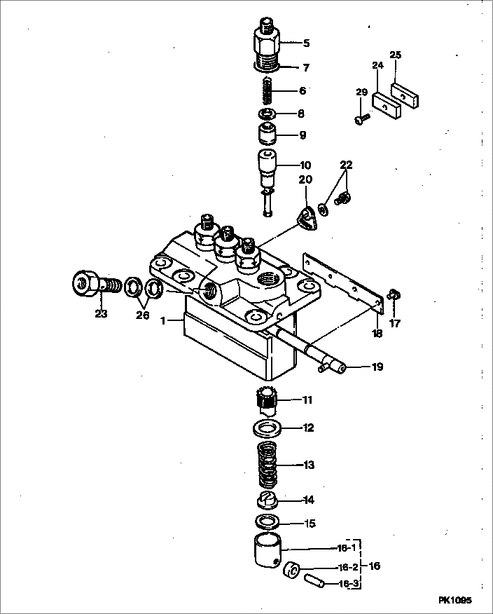
| 000. | [01] | 09450-04860 | PUMP ASSY, INJECTI | 16475-51014 |
| 001. | [01] | 09011-01332 | HOUSING SUB-ASSY, | |
| 005. | [04] | 09013-00450 | HOLDER SUB-ASSY, D | 16415-51221 |
| 006. | [04] | 09013-60960 | SPRING, DELIVERY V | 16415-51231 |
| 007. | [04] | 90802-20150 | O-RING | 14611-51201 |
| 008. | [04] | 09013-70061 | GASKET, DELIVERY V | 15221-51241 |
| 008. | [04] | 09013-70130 | GASKET, DELIVERY V | 11420-51241 |
| 009. | [04] | 09014-00620 | VALVE SUB-ASSY, IN | 15271-51031 |
| 010. | [04] | 09015-04430 | ELEMENT SUB-ASSY, | 16415-51051 |
| 011. | [04] | 09016-10210 | SLEEVE, PLUNGER CO | 15221-51382 |
| 012. | [04] | 09016-30082 | SEAT, SPRING, UPR | 15221-51271 |
| 013. | [04] | 09016-40170 | SPRING, PUMP PLUNG | 15221-51281 |
| 014. | [04] | 09030-10060 | SEAT, SPRING, LWR | 15021-51291 |
| 015. | [4C] | 09031-10310 | PLATE, TAPPET ADJU | |
| 015. | [4C] | 09031-10300 | PLATE, TAPPET ADJU | |
| 015. | [4C] | 09031-10280 | PLATE, TAPPET ADJU | |
| 015. | [4C] | 09031-10170 | PLATE, TAPPET ADJU | |
| 015. | [4C] | 09031-10160 | PLATE, TAPPET ADJU | |
| 015. | [4C] | 09031-10140 | PLATE, TAPPET ADJU | |
| 015. | [4C] | 09031-10130 | PLATE, TAPPET ADJU | 15221-51491 |
| 015. | [4C] | 09031-10120 | PLATE, TAPPET ADJU | |
| 015. | [4C] | 09031-10110 | PLATE, TAPPET ADJU | |
| 015. | [4C] | 09031-10010 | PLATE, TAPPET ADJU | 14109-51301 |
| 016. | [04] | 09017-00170 | TAPPET SUB-ASSY,IN | 15221-51071 |
| 016-001. | [04] | 09017-10021 | TAPPET, INJECTION | 15021-51990 |
| 016-002. | [04] | 09217-60010 | ROLLER, FEED PUMP | 15109-52931 |
| 016-003. | [04] | 09017-60020 | PIN, INJECTION PUM | 15021-51970 |
| 017. | [04] | 09018-30050 | PIN, INJECTION PUM | 14611-51251 |
| 018. | [02] | 09046-70030 | PLATE | 14611-51441 |
| 019. | [01] | 09021-00251 | RACK ASSY, CONTROL | 15401-51061 |
| 020. | [03] | 09006-80020 | PLATE, ADJUSTING | 14384-51391 |
| 022. | [03] | 94904-71980 | BOLT, W/WASHER | 15221-91031 |
| 022. | [03] | 94904-80800 | BOLT, WASHER HEAD | |
| 023. | [01] | 09024-50170 | SCREW, HOLLOW | 15471-51321 |
| 024. | [02] | 09023-10080 | PLATE, DELIVERY VA | |
| 025. | [02] | 09023-20080 | PLATE, DELIVERY VA | |
| 025. | [02] | 09023-20050 | PLATE, DELIVERY VA | |
| 026. | [02] | 09022-20050 | WASHER, FUEL PIPE | 15401-96652 |
| 029. | [02] | 94904-44330 | BOLT |
Include in #3:
09450-04860
as PUMP ASSY, INJECTI
Cross reference number
| Part num | Firm num | Firm | Name |
| 09450-04860 | 16475-5101 | PUMP ASSY, INJECTI | |
| 16475-51014 | KUBOTA | PUMP ASSY, INJECTI |
Information:
2. Remove the two bolts (1) from transfer pump, and pull the pump out of accessory drive housing.3. Remove the four bolts and lock from retainer (3). Remove the retainer.4. Remove the drive gear (2). 5. Remove the two bolts, locks, and plate (5).6. Remove the variable timing unit (4) from the accessory drive housing.Install Variable Timing Unit
1. Put the variable timing unit (1) in position in the accessory drive housing.2. Install the retaining plate, locks, and two bolts.3. Install the drive gear, retainer, lock, and four bolts. Do not tighten the four bolts.4. Make an adjustment to the timing of the camshaft for the fuel injection pump. See FUEL INJECTION PUMP CAMSHAFT TIMING in TESTING AND ADJUSTING. 5. Install the cover (4) on timing gear housing.6. Put the transfer pump (3) in position on the accessory drive housing, and install the two bolts (2).7. Check to be sure all timing pins and bolts have been removed from their timing holes, and are installed in their storage positions.Disassemble Variable Timing Unit
start by: a) remove variable timing unit 1. Push down on retainer (1), and remove the pin (2).2. Remove the retainer and spring. 3. Use a hammer and punch to remove the dowels (4). Remove the two weights.4. Remove the piston and rod assembly (5) from shaft assembly (3).5. Remove the pins from nut and rod.6. Remove the rod, nut, spring, and valve from the piston assembly.Assemble Variable Timing Unit
1. Install the valve, spring, and nut on the piston assembly. Turn the nut until the distance (X) between bottom face of nut and the piston is 1.760 in. (44.7 mm). Drill a .095 .002 in. (2.41 0.05 mm) diameter hole through the nut and the threads of piston assembly. Install the pin in nut. 1. Install the rod tight against the nut. Take a measurement .156 in. (3.96 mm) from top face of nut, and put a mark at this location on rod. Drill a .095 .0.05 mm) diameter hole (1) through the rod and piston assembly at this location. Install the pin in rod.3. Install the piston and rod assembly in the shaft assembly. Install the spring, retainer, and pin in shaft assembly.4. Install the weights and dowels. Use a hammer and punch to fasten both ends of the dowels in place. Both weights must move freely after the dowels have been fastened in place.end by: a) install variable timing unit