Information pump assy, injecti
Rating:
Components :
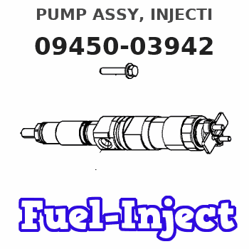
| 001. | PUMP ASSY, INJECTI | 09450-03942 |
Scheme ###:
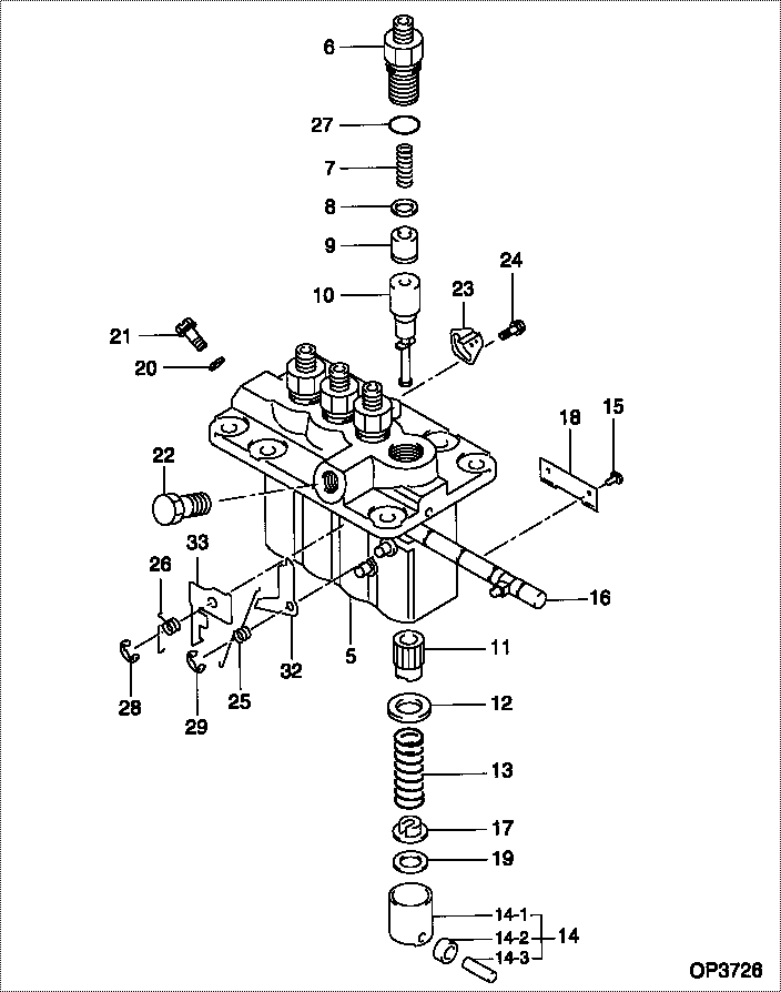
| 000. | [01] | 09450-03942 | PUMP ASSY, INJECTI | MM434611 |
| 005. | [01] | 09011-02420 | HOUSING SUB-ASSY, | MM501253 |
| 006. | [04] | 09013-10720 | HOLDER, DELIVERY V | MM501754 |
| 007. | [04] | 09013-60900 | SPRING, DELIVERY V | MM514003 |
| 008. | [04] | 09013-70130 | GASKET, DELIVERY V | MM501856 |
| 009. | [04] | 09014-02030 | VALVE SUB-ASSY, IN | MM514165 |
| 010. | [04] | 09015-04640 | ELEMENT SUB-ASSY, | MM514166 |
| 011. | [04] | 09016-10210 | SLEEVE, PLUNGER CO | MM500229 |
| 012. | [04] | 09016-30082 | SEAT, SPRING, UPR | MM501098 |
| 013. | [04] | 09016-40170 | SPRING, PUMP PLUNG | MM500360 |
| 014. | [04] | 09017-00170 | TAPPET SUB-ASSY,IN | MM500230 |
| 014-001. | [04] | 09017-10022 | TAPPET, INJECTION | |
| 014-002. | [04] | 09217-60010 | ROLLER, FEED PUMP | ME702227 |
| 014-003. | [04] | 09017-60020 | PIN, INJECTION PUM | P720-1429 |
| 015. | [04] | 09018-30050 | PIN, INJECTION PUM | MM500231 |
| 016. | [01] | 09021-00440 | RACK ASSY, CONTROL | MM501255 |
| 017. | [04] | 09030-10060 | SEAT, SPRING, LWR | MM500316 |
| 018. | [02] | 09046-70030 | PLATE | MM500232 |
| 019. | [4C] | 09031-10310 | PLATE, TAPPET ADJU | MM501365 |
| 019. | [4C] | 09031-10300 | PLATE, TAPPET ADJU | MM501364 |
| 019. | [4C] | 09031-10280 | PLATE, TAPPET ADJU | MM501246 |
| 019. | [4C] | 09031-10170 | PLATE, TAPPET ADJU | P760-15160 |
| 019. | [4C] | 09031-10160 | PLATE, TAPPET ADJU | MM500314 |
| 019. | [4C] | 09031-10140 | PLATE, TAPPET ADJU | MM500312 |
| 019. | [4C] | 09031-10130 | PLATE, TAPPET ADJU | MM500311 |
| 019. | [4C] | 09031-10120 | PLATE, TAPPET ADJU | MM500310 |
| 019. | [4C] | 09031-10110 | PLATE, TAPPET ADJU | MM500309 |
| 019. | [4C] | 09031-10010 | PLATE, TAPPET ADJU | ME702559 |
| 020. | [01] | 94901-81020 | WASHER, COPPER PLA | ME022309 |
| 021. | [01] | 09314-10170 | NIPPLE, OIL LEAKAG | MM500909 |
| 022. | [01] | 94918-00310 | SCREW, HOLLOW | ME702236 |
| 023. | [03] | 09006-80020 | PLATE, ADJUSTING | MM514109 |
| 024. | [03] | 94904-80800 | BOLT, WASHER HEAD | |
| 025. | [01] | 09055-40470 | SPRING, DIAPHRAGM | MM514131 |
| 026. | [01] | 09055-40280 | SPRING, DIAPHRAGM | MM501247 |
| 027. | [04] | 09013-90410 | O-RING | |
| 027. | [04] | 90802-20150 | O-RING | |
| 028. | [01] | 09089-40020 | E-RING | ME702639 |
| 029. | [01] | 09089-40010 | E-RING | ME702112 |
| 032. | [1C] | 09021-95370 | STOPPER | MM501748 |
| 032. | [1C] | 09021-95360 | STOPPER | |
| 032. | [1C] | 09021-93120 | STOPPER | MM501501 |
| 032. | [1C] | 09021-93110 | STOPPER | MM501500 |
| 032. | [1C] | 09021-93100 | STOPPER | MM501499 |
| 032. | [1C] | 09021-93090 | STOPPER | MM501498 |
| 032. | [1C] | 09021-93080 | STOPPER | MM501497 |
| 033. | [1C] | 09021-93660 | STOPPER | MM501271 |
| 033. | [1C] | 09021-93670 | STOPPER | MM501571 |
| 033. | [1C] | 09021-93680 | STOPPER | MM501272 |
| 033. | [1C] | 09021-93690 | STOPPER | MM501572 |
| 033. | [1C] | 09021-93700 | STOPPER | |
| 033. | [1C] | 09021-93710 | STOPPER | |
| 033. | [1C] | 09021-93650 | STOPPER | MM501570 |
| 033. | [1C] | 09021-93640 | STOPPER | MM501270 |
| 033. | [1C] | 09021-93630 | STOPPER | MM501569 |
| 033. | [1C] | 09021-93620 | STOPPER | MM501269 |
| 033. | [1C] | 09021-93610 | STOPPER | MM501568 |
| 033. | [1C] | 09021-93600 | STOPPER | MM501268 |
| 033. | [1C] | 09021-93590 | STOPPER | MM501567 |
| 033. | [1C] | 09021-93580 | STOPPER | MM501267 |
| 033. | [1C] | 09021-93720 | STOPPER |
Include in #3:
09450-03942
as PUMP ASSY, INJECTI
Cross reference number
| Part num | Firm num | Firm | Name |
| 09450-03942 | MM434611 | PUMP ASSY, INJECTI |
Information:
The fuel system consists of the transfer pump, fuel filter, shutoff solenoid, injection pumps, timing advance unit, governor, injection lines, nozzles and excess fuel return lines.The diaphragm-type fuel transfer pump mounts on the fuel injection pump housing and is driven by a lobe on the injection pump camshaft. The pump draws fuel from the vehicle supply tank and delivers it to a spin-on throw-away type filter. The filter is a combination primary-secondary element.Filtered fuel flows through a fuel shutoff solenoid, mounted on the fuel injection pump housing, into a fuel manifold. The solenoid operates electrically and stops fuel flow when the vehicle ignition system is off.Fuel in the manifold flows through the barrel assembly inlet port into the area above the injection pump plunger. During injection, the camshaft forces the plunger upward in the barrel. The end of the plunger closes the inlet port and forces the fuel out through high pressure injection lines to the nozzles.The injection nozzles are located under the valve cover and are held in place by clamps. The nozzle tip projects from the head into the cylinder bore. Atomized fuel is sprayed in a cone-shaped pattern through four orifices into the cylinder.During injection, a small amount of fuel leaks past the valve guide in the nozzle body to lubricate its moving parts. Any excess leakage flows from the nozzle to a fuel return manifold under the valve cover of each cylinder head. External lines connect the manifolds and return the fuel to the tank.Fuel Injection Pump Operation
Fuel enters the fuel injection pump housing from the fuel filter through the fuel manifold and goes to the fuel injection pump through inlet port. The injection pump plungers and lifters are lifted by the cam lobes on the injection pump camshaft and always make a full stroke. Springs hold the lifters against the cam lobes. Each pump meters the amount of fuel injected into its respective cylinder and delivers it to the fuel injector. The amount of fuel pumped per stroke is varied by the turning of the plunger in its barrel. Each plunger is turned by the action of the governor through a gear segmented sliding rack turning the gear segment on the bottom of the pump plunger. The position of the scroll on the plunger determines the amount of fuel to be injected into the cylinder. Figures A, B and C illustrate the function of an injection pump as the plunger makes a stroke.In Fig. A the plunger is down and the inlet port is uncovered. Fuel flows into the space above the plunger, through the slot and into the recess around the plunger.In Fig. B, the plunger has started up and the port is covered. Fuel is trapped and is forced through a check valve, fuel line, and injector as the plunger moves upward.In Fig. C the plunger has risen until the port is uncovered by the recess in the plunger. The fuel now can escape back through the port into the fuel
Fuel enters the fuel injection pump housing from the fuel filter through the fuel manifold and goes to the fuel injection pump through inlet port. The injection pump plungers and lifters are lifted by the cam lobes on the injection pump camshaft and always make a full stroke. Springs hold the lifters against the cam lobes. Each pump meters the amount of fuel injected into its respective cylinder and delivers it to the fuel injector. The amount of fuel pumped per stroke is varied by the turning of the plunger in its barrel. Each plunger is turned by the action of the governor through a gear segmented sliding rack turning the gear segment on the bottom of the pump plunger. The position of the scroll on the plunger determines the amount of fuel to be injected into the cylinder. Figures A, B and C illustrate the function of an injection pump as the plunger makes a stroke.In Fig. A the plunger is down and the inlet port is uncovered. Fuel flows into the space above the plunger, through the slot and into the recess around the plunger.In Fig. B, the plunger has started up and the port is covered. Fuel is trapped and is forced through a check valve, fuel line, and injector as the plunger moves upward.In Fig. C the plunger has risen until the port is uncovered by the recess in the plunger. The fuel now can escape back through the port into the fuel