Information pump assy, injecti
Nozzle:
0935002240
Rating:
Components :
| 001. | PUMP ASSY, INJECTI | 09450-03920 |
| 001. | PUMP ASSY, INJECTI | 09450-03920 |
Scheme ###:
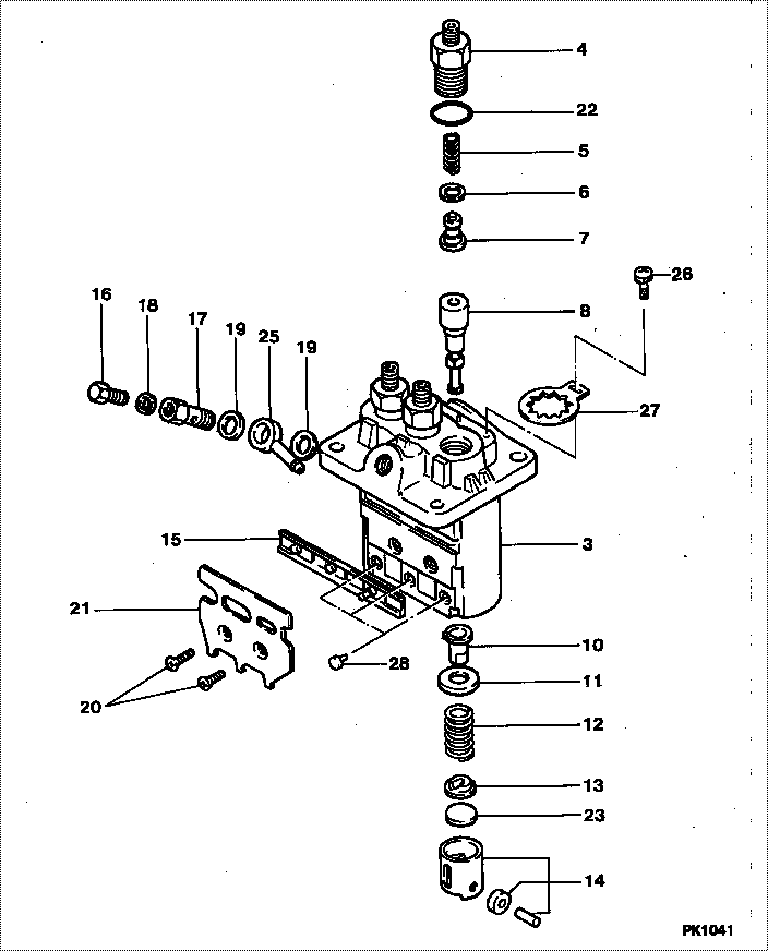
| 000. | [01] | 09450-03920 | PUMP ASSY, INJECTI | 131017340 |
| 000. | [01] | 09450-03920 | PUMP ASSY, INJECTI | 131017341 |
| 003. | [01] | 09011-03680 | HOUSING SUB-ASSY, | 131296665 |
| 004. | [03] | 09013-10830 | HOLDER, DELIVERY V | 131196120 |
| 005. | [03] | 09013-60530 | SPRING, DELIVERY V | 131176430 |
| 006. | [03] | 09013-70130 | GASKET, DELIVERY V | 131186050 |
| 006. | [03] | 09013-70061 | GASKET, DELIVERY V | 131186100 |
| 007. | [03] | 09014-01670 | VALVE SUB-ASSY, IN | 131156160 |
| 008. | [03] | 09015-04080 | ELEMENT SUB-ASSY, | 131116410 |
| 010. | [03] | 09016-00140 | SLEEVE SUB-ASSY, C | 131296950 |
| 011. | [03] | 09016-30140 | SEAT, SPRING, UPR | 131296620 |
| 012. | [03] | 09016-40220 | SPRING, PUMP PLUNG | 131176440 |
| 013. | [03] | 09016-50170 | SEAT, SPRING, LWR | 131296621 |
| 014. | [03] | 09017-00220 | TAPPET SUB-ASSY,IN | 131256120 |
| 015. | [01] | 09021-00500 | RACK ASSY, CONTROL | 131296636 |
| 016. | [01] | 09024-40010 | SCREW, AIR BLEEDER | 131236201 |
| 017. | [01] | 09024-50240 | SCREW, HOLLOW | 131236190 |
| 018. | [01] | 09024-80010 | WASHER, DRAIN SCRE | 131426190 |
| 019. | [02] | 09025-10010 | WASHER, INJECTION | 131426180 |
| 020. | [02] | 94900-20500 | SCREW, COUNTERSUNK | 131136320 |
| 021. | [01] | 09069-11020 | BRACKET, STOP WIRE | 131296650 |
| 022. | [03] | 09013-90400 | O-RING | |
| 022. | [03] | 90801-10130 | O-RING | 131226170 |
| 023. | [ C] | 09031-10450 | PLATE, TAPPET ADJU | 131296635 |
| 023. | [ C] | 09031-10440 | PLATE, TAPPET ADJU | 131296634 |
| 023. | [ C] | 09031-10430 | PLATE, TAPPET ADJU | 131296633 |
| 023. | [ C] | 09031-10420 | PLATE, TAPPET ADJU | 131296632 |
| 023. | [ C] | 09031-10410 | PLATE, TAPPET ADJU | 131296631 |
| 023. | [ C] | 09031-10400 | PLATE, TAPPET ADJU | 131296630 |
| 023. | [ C] | 09031-10390 | PLATE, TAPPET ADJU | 131296629 |
| 023. | [ C] | 09031-10380 | PLATE, TAPPET ADJU | 131296628 |
| 023. | [ C] | 09031-10320 | PLATE, TAPPET ADJU | 131296622 |
| 023. | [ C] | 09031-10330 | PLATE, TAPPET ADJU | 131296623 |
| 023. | [ C] | 09031-10340 | PLATE, TAPPET ADJU | 131296624 |
| 023. | [ C] | 09031-10350 | PLATE, TAPPET ADJU | 131296625 |
| 023. | [ C] | 09031-10360 | PLATE, TAPPET ADJU | 131296626 |
| 023. | [ C] | 09031-10370 | PLATE, TAPPET ADJU | 131296627 |
| 025. | [01] | 94918-10430 | NIPPLE, SWIVELING | 131246130 |
| 026. | [03] | 91370-05101 | SCREW, W/WASHER | 131136330 |
| 026. | [03] | 94900-75390 | SCREW, W/WASHER | 131136330 |
| 027. | [03] | 09023-00070 | PLATE SET, VALVE H | 131296662 |
| 028. | [03] | 09018-30090 | PIN, INJECTION PUM | 131296651 |
Include in #3:
09450-03920
as PUMP ASSY, INJECTI
09450-03920
Cross reference number
| Part num | Firm num | Firm | Name |
| 09450-03920 | 131017340 | PUMP ASSY, INJECTI | |
| 131017341 | ISHIKAWAJIMA | PUMP ASSY, INJECTI | |
| 131017340 | ISHIKAWAJIMA | PUMP ASSY, INJECTI |
Information:
The air cleaner service indicator is connected to the air inlet pipe between the air cleaner and the manifold. It contains a red marked piston, which gradually rises with restriction to the air flow. When the entire piston is visible it will lock in this position. This indicates a need for air cleaner service. The piston will remain in this position whether or not the engine is running. After servicing the air cleaner, reset the piston by depressing the plunger in the bottom of the indicator.Excessive engine exhaust smoke and/or loss of power may indicate the need for servicing the air cleaner. Never service the air cleaner while the engine is running.(See your truck manufacturer's operator's books for maintenance intervals and instructions.) Air cleaner restriction at high idle should not exceed 25 inches (635 mm) of water.Valve Lash
Make valve lash adjustment with engine stopped.Top dead center (TDC) of the No. 1 piston on the compression stroke is the reference point. The No. 1 piston is at TDC compression stroke when the timing mark on the crankshaft damper or the pulley is aligned with the timing pointer, and No. 1 and No. 2 exhaust and inlet valves are closed. (The rocker arms are free.) To Adjust The Valve Lash
1. Adjust lash for No. 1 and No. 2 exhaust and inlet valves. a. Loosen valve adjusting screw locknut.b. Turn adjusting screw to allow a clearance gauge to pass between the top of the valve stem and the valve rocker arm. c. Set lash at .025 in. (0,64 mm) for exhaust valves and .015 in. (0,38 mm) for inlet valves.d. Tighten adjusting screw locknut.e. Check adjustment. 2. Turn crankshaft 180° clockwise (viewed from front of engine). Some engines have a "VS" mark directly opposite the TDC mark. Align the "VS" mark with the pointer. Adjust lash for No. 7 and No. 3 exhaust and inlet valves.3. Turn crankshaft 180° clockwise (viewed from front of engine). Timing mark (TDC) and pointer should be aligned. Adjust lash for No. 4 and No. 5 exhaust and inlet valves.4. Turn crankshaft 180° clockwise (viewed from front of engine). "VS" mark and pointer should be aligned. Adjust lash for No. 6 and No. 8 exhaust and inlet valves. POSITIVE CRANKCASE VENTILATION VALVE: The PCV valve directs blow-by gases to the combustion chambers where they are burned. Scheduled maintenance or adjustment is not required; however any oily accumulation around the cover could indicate the diaphragm has worn through. Replace diaphragm every 48,000 miles or 1,200 service hours.Replacing Diaphragm:1. Clean area around PCV valve (1).2. Remove series of bolts holding cover (2) in place.3. Clean and inspect all parts and replace as necessary. Always install new gaskets and diaphragm when disassembled for inspection. 4. When installing, coat both sides of the gasket (4) with gasket cement and install against rear face of inner sleeve (3).5. To prevent diaphragm (6) from distorting and tearing during assembly, coat both flange sides of the diaphragm with gasket cement and install