Information pump assy, injecti
Nozzle:
0935001660
Rating:
Components :
| 001. | PUMP ASSY, INJECTI | 09450-02560 |
Scheme ###:
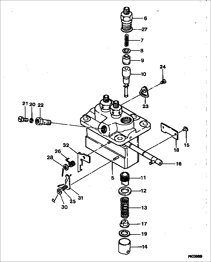
| 000. | [01] | 09450-02560 | PUMP ASSY, INJECTI | MM409848 |
| 005. | [01] | 09011-02590 | HOUSING SUB-ASSY, | MM501312 |
| 006. | [03] | 09013-10520 | HOLDER, DELIVERY V | MM501507 |
| 007. | [03] | 09013-60540 | SPRING, DELIVERY V | MM501161 |
| 008. | [03] | 09013-70061 | GASKET, DELIVERY V | P720-16141 |
| 008. | [03] | 09013-70130 | GASKET, DELIVERY V | MM501856 |
| 009. | [03] | 09014-00800 | VALVE SUB-ASSY, IN | MM501076 |
| 010. | [03] | 09015-02680 | ELEMENT SUB-ASSY, | MM501335 |
| 011. | [03] | 09016-10210 | SLEEVE, PLUNGER CO | MM500229 |
| 012. | [03] | 09016-30082 | SEAT, SPRING, UPR | MM501098 |
| 013. | [03] | 09016-40170 | SPRING, PUMP PLUNG | MM500360 |
| 014. | [03] | 09017-00170 | TAPPET SUB-ASSY,IN | MM500230 |
| 014-001. | [03] | 09017-10022 | TAPPET, INJECTION | |
| 014-002. | [03] | 09217-60010 | ROLLER, FEED PUMP | ME702227 |
| 014-003. | [03] | 09017-60020 | PIN, INJECTION PUM | P720-1429 |
| 015. | [03] | 09018-30050 | PIN, INJECTION PUM | MM500231 |
| 016. | [01] | 09021-00470 | RACK ASSY, CONTROL | MM501311 |
| 017. | [03] | 09030-10060 | SEAT, SPRING, LWR | MM500316 |
| 018. | [01] | 09046-70040 | PLATE | MM501162 |
| 019. | [ C] | 09031-10310 | PLATE, TAPPET ADJU | MM501365 |
| 019. | [ C] | 09031-10300 | PLATE, TAPPET ADJU | MM501364 |
| 019. | [ C] | 09031-10280 | PLATE, TAPPET ADJU | MM501246 |
| 019. | [ C] | 09031-10170 | PLATE, TAPPET ADJU | P760-15160 |
| 019. | [ C] | 09031-10160 | PLATE, TAPPET ADJU | MM500314 |
| 019. | [ C] | 09031-10140 | PLATE, TAPPET ADJU | MM500312 |
| 019. | [ C] | 09031-10130 | PLATE, TAPPET ADJU | MM500311 |
| 019. | [ C] | 09031-10120 | PLATE, TAPPET ADJU | MM500310 |
| 019. | [ C] | 09031-10110 | PLATE, TAPPET ADJU | MM500309 |
| 019. | [ C] | 09031-10010 | PLATE, TAPPET ADJU | ME702559 |
| 020. | [01] | 09022-20080 | WASHER, FUEL PIPE | ME702235 |
| 020. | [01] | 94901-81020 | WASHER, COPPER PLA | ME022309 |
| 021. | [01] | 09024-40180 | SCREW, AIR BLEEDER | MM501152 |
| 022. | [01] | 09024-50210 | SCREW, HOLLOW | MM501320 |
| 023. | [02] | 09007-00012 | PLATE ASSY, ADJUST | MM501077 |
| 023. | [02] | 09006-80020 | PLATE, ADJUSTING | MM514109 |
| 024. | [02] | 94904-71980 | BOLT, W/WASHER | MM501244 |
| 024. | [02] | 94904-80800 | BOLT, WASHER HEAD | |
| 025. | [01] | 09055-40300 | SPRING, DIAPHRAGM | MM501256 |
| 026. | [01] | 09055-40160 | SPRING, DIAPHRAGM | MM501073 |
| 027. | [03] | 90802-20150 | O-RING | MM500438 |
| 028. | [01] | 09089-40020 | E-RING | ME702639 |
| 030. | [01] | 09089-40010 | E-RING | ME702112 |
| 031. | [ C] | 09021-92540 | STOPPER | MM501275 |
| 031. | [ C] | 09021-92530 | STOPPER | MM501260 |
| 031. | [ C] | 09021-92520 | STOPPER | MM501259 |
| 031. | [ C] | 09021-92510 | STOPPER | MM501258 |
| 031. | [ C] | 09021-92500 | STOPPER | MM501257 |
| 032. | [ C] | 09021-93800 | STOPPER | MM501388 |
| 032. | [ C] | 09021-93780 | STOPPER | MM501387 |
| 032. | [ C] | 09021-93760 | STOPPER | MM501386 |
| 032. | [ C] | 09021-93740 | STOPPER | |
| 032. | [ C] | 09021-93720 | STOPPER | |
| 032. | [ C] | 09021-93700 | STOPPER | |
| 032. | [ C] | 09021-93680 | STOPPER | MM501272 |
| 032. | [ C] | 09021-93660 | STOPPER | MM501271 |
| 032. | [ C] | 09021-93640 | STOPPER | MM501270 |
| 032. | [ C] | 09021-93820 | STOPPER | MM501395 |
Include in #3:
09450-02560
as PUMP ASSY, INJECTI
Cross reference number
| Part num | Firm num | Firm | Name |
| 09450-02560 | MM409848 | PUMP ASSY, INJECTI | |
| MM409848 | MITSUBISHI | PUMP ASSY, INJECTI |
Information:
When testing fuel injection nozzles, always wear eye protection. Fuel comes from the orifices in the nozzle tip under high pressure and can pierce the skin and cause serious injury to the operator. Always keep the tip of the nozzle pointed away from the operator and into the 8S2270 Fuel Collector and FT1384 Extension.
Some of the tools shown in this instruction are not now available from Caterpillar. The tools are shown for reference only. (1) Use the 5B1401 Cleaning Tool Group to clean carbon from the nozzle end orifice; use a .0175" drill for 3 3/4" bore engines with heavy rated springs, .0197" drill for other 3 3/4" bore and all 4 1/4" bore engines, or a .024" drill for 5 1/4", 5 3/4" and 6 1/8" bore engines. Cover the fuel inlet and overflow openings with the covers provided, and clean the exterior of the valve with cleaning solvent or diesel fuel. (2) Use 5P7448 Adapter (1) and 5P4721 Tube (A) to connect the valve to the nozzle tester. Close gauge protector valves (2), (3) and (4) and on-off valve (5). Open pump isolator valve (6).(3) Spray Pattern and Fuel Cutoff (Except 1P1795 Master Valves) A. Pump the tester to remove air from the line.B. Pump the tester with short, fast strokes and look at the spray pattern and fuel cutoff.C. If the spray pattern and fuel cutoff are not satisfactory, see CLEANING, NEEDLE, NOZZLE BORE AND NOZZLE END OF FLAT-SEAT VALVES.D. If, after cleaning, the spray pattern and fuel cutoff are still not satisfactory, install a new valve service group. (4) VOP (Valve Opening Pressure) Test A. Open the gauge protector valve [0-34500 kPa (0-5000 psi) gauge].B. Increase the pressure until test oil flows from the nozzle tip.C. Write down the VOP. (5) Pressure Loss Test A. Increase the pressure to 690 kPa (100 psi) less than the VOP.B. Close the pump isolator valve (6).C. Use the gauge protector valve (3), [0-34500 kPa (0-5000 psi) gauge] to adjust pressure to 690 kPa (100 psi) less than the VOP.D. After 30 seconds, write down the pressure loss. (6) Adjustment of Valve Opening Pressure If spray characteristics are satisfactory, adjust the valve unseating pressure: Use 7B2591 Cap Wrench (7) to remove the cap. Remove lift screw locknut (8) and loosen lift adjustment screw (9) approximately three turns, so it does not interfere with the pressure adjustment. Loosen pressure adjustment locknut (10).E. Install the nozzle on the 5P4150 Nozzle Tester. F. Use 7B2601 Wrench (11) and adjust the VOP. G. Remove the valve from the nozzle tester and put it in a vise. Install lift adjustment screw locknut (8).H. Use the 6B1655 Wrench to turn lift adjusting screw (9) down lightly against the stem of the fuel valve spring.I. Clamp the needle lift adjustment fixture to the fuel valve body.J. Use a thickness gauge and adjust screw (12) until there is a clearance of 0.43 (.017") between screw (12) and lift adjustment screw (9).K. Hold screw (12)