Information pump assy, injecti
Nozzle:
0935002310
Rating:
Components :
| 001. | PUMP ASSY, INJECTI | 09450-02510 |
Scheme ###:
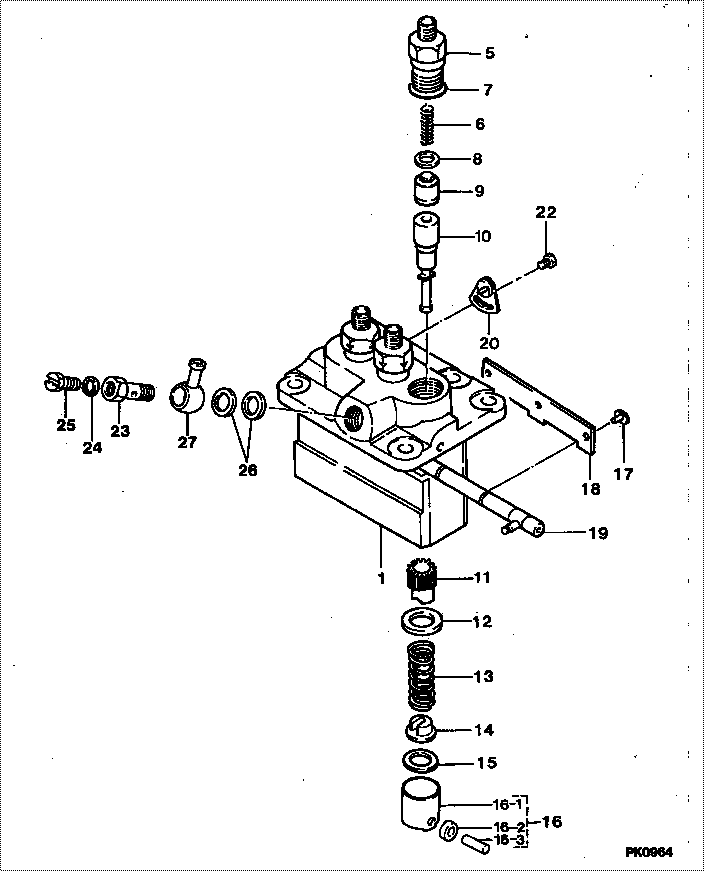
| 000. | [01] | 09450-02510 | PUMP ASSY, INJECTI | 35430-163-20A |
| 001. | [01] | 09011-03020 | HOUSING SUB-ASSY, | |
| 005. | [03] | 09013-10520 | HOLDER, DELIVERY V | |
| 006. | [03] | 09013-60540 | SPRING, DELIVERY V | |
| 007. | [03] | 90802-20150 | O-RING | |
| 008. | [03] | 09013-70061 | GASKET, DELIVERY V | |
| 008. | [03] | 09013-70130 | GASKET, DELIVERY V | |
| 009. | [03] | 09014-00800 | VALVE SUB-ASSY, IN | |
| 010. | [01] | 09015-03020 | ELEMENT SUB-ASSY, | |
| 011. | [03] | 09016-10100 | SLEEVE, PLUNGER CO | |
| 011. | [03] | 09016-10210 | SLEEVE, PLUNGER CO | |
| 012. | [03] | 09016-30082 | SEAT, SPRING, UPR | |
| 013. | [03] | 09016-40170 | SPRING, PUMP PLUNG | |
| 014. | [03] | 09030-10060 | SEAT, SPRING, LWR | |
| 015. | [ C] | 09031-10170 | PLATE, TAPPET ADJU | |
| 015. | [ C] | 09031-10160 | PLATE, TAPPET ADJU | |
| 015. | [ C] | 09031-10140 | PLATE, TAPPET ADJU | |
| 015. | [ C] | 09031-10130 | PLATE, TAPPET ADJU | |
| 015. | [ C] | 09031-10120 | PLATE, TAPPET ADJU | |
| 015. | [ C] | 09031-10110 | PLATE, TAPPET ADJU | |
| 015. | [ C] | 09031-10010 | PLATE, TAPPET ADJU | |
| 016. | [03] | 09017-00170 | TAPPET SUB-ASSY,IN | |
| 016-001. | [03] | 09017-10021 | TAPPET, INJECTION | |
| 016-002. | [03] | 09217-60010 | ROLLER, FEED PUMP | |
| 016-003. | [03] | 09017-60020 | PIN, INJECTION PUM | |
| 017. | [03] | 09018-30050 | PIN, INJECTION PUM | |
| 018. | [01] | 09018-50020 | PIN, CLAMP | |
| 018. | [01] | 09046-70040 | PLATE | |
| 019. | [01] | 09021-00490 | RACK ASSY, CONTROL | |
| 020. | [02] | 09007-00012 | PLATE ASSY, ADJUST | |
| 020. | [02] | 09006-80020 | PLATE, ADJUSTING | |
| 022. | [02] | 94904-71980 | BOLT, W/WASHER | |
| 022. | [02] | 94904-80800 | BOLT, WASHER HEAD | |
| 023. | [01] | 09024-50210 | SCREW, HOLLOW | |
| 024. | [01] | 94901-81020 | WASHER, COPPER PLA | |
| 025. | [01] | 09024-40080 | SCREW, AIR BLEEDER | |
| 026. | [02] | 09024-10010 | WASHER, AIR BLEEDE | |
| 027. | [01] | 94918-10150 | NIPPLE, SWIVELING |
Include in #3:
09450-02510
as PUMP ASSY, INJECTI
Cross reference number
| Part num | Firm num | Firm | Name |
| 09450-02510 | 35430-163- | PUMP ASSY, INJECTI | |
| 35430-163-20A | KAWASAKI | PUMP ASSY, INJECTI |
Information:
Illustrations show fuel injection pump housing and governor removed from engines. Service work can be done with it installed on engine. 1. Remove the flange (1) and flange assembly (2) from the cover (3).2. Remove the cover from the pump housing by removing seven bolts. 3. Remove the solenoid (4) from the cover.4. Remove cover (6).5. Remove two bolts (5) that hold the cover to the shutoff housing. 6. Remove the cover from the shutoff housing (7). 7. Remove the lever (10) from the shaft (11).8. Remove the shaft (9) from the shutoff housing.9. Remove the lever (8) from the shaft (11).10. Remove the shaft (11) from the shutoff housing.11. Remove the seal (12) from the shutoff housing.Install Shutoff Housing
1. Put 5S1454 Sealing Compound on the outside diameter of the seal and install the seal (1) with tooling (A) in the shutoff housing with the lip toward the outside. The outer face of the seal must be .039 in. (1.0 mm) below the surface of the housing. Remove the extra sealing compound from the housing and the seal after installation. 2. Install the shaft (3) in the shutoff housing.3. Install the lever (5) on the shaft (3).4. Install shaft (2) in the shutoff housing.5. Install the lever (4) on shaft (3). 6. Put the cover (6) in position on the shutoff housing and install two bolts that hold the cover to the housing. 7. Install the cover (8).8. Install the solenoid (7) on the cover.9. Install the cover (6) on the pump housing.10. Install the flange assembly and the flange on the cover.
1. Put 5S1454 Sealing Compound on the outside diameter of the seal and install the seal (1) with tooling (A) in the shutoff housing with the lip toward the outside. The outer face of the seal must be .039 in. (1.0 mm) below the surface of the housing. Remove the extra sealing compound from the housing and the seal after installation. 2. Install the shaft (3) in the shutoff housing.3. Install the lever (5) on the shaft (3).4. Install shaft (2) in the shutoff housing.5. Install the lever (4) on shaft (3). 6. Put the cover (6) in position on the shutoff housing and install two bolts that hold the cover to the housing. 7. Install the cover (8).8. Install the solenoid (7) on the cover.9. Install the cover (6) on the pump housing.10. Install the flange assembly and the flange on the cover.