Information pump assy, injecti
Nozzle:
0935001660
Rating:
Components :
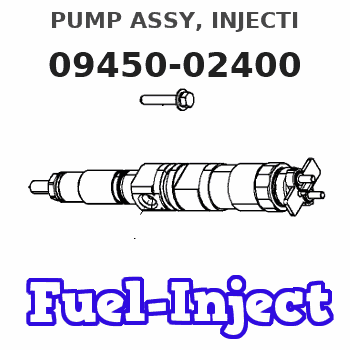
| 001. | PUMP ASSY, INJECTI | 09450-02400 |
Scheme ###:
| 000. | [01] | 09450-02400 | PUMP ASSY, INJECTI | MM402950 |
| 005. | [01] | 09011-01441 | HOUSING SUB-ASSY, | MM500225 |
| 006. | [02] | 09013-10280 | HOLDER, DELIVERY V | MM501075 |
| 006. | [02] | 09013-10520 | HOLDER, DELIVERY V | MM501507 |
| 007. | [02] | 09013-60480 | SPRING, DELIVERY V | MM501047 |
| 008. | [02] | 09013-70061 | GASKET, DELIVERY V | P720-16141 |
| 008. | [02] | 09013-70130 | GASKET, DELIVERY V | MM501856 |
| 009. | [02] | 09014-01300 | VALVE SUB-ASSY, IN | MM501380 |
| 010. | [02] | 09015-02011 | ELEMENT SUB-ASSY, | MM501154 |
| 011. | [02] | 09016-10210 | SLEEVE, PLUNGER CO | MM500229 |
| 012. | [02] | 09016-30082 | SEAT, SPRING, UPR | MM501098 |
| 013. | [02] | 09016-40170 | SPRING, PUMP PLUNG | MM500360 |
| 014. | [02] | 09030-10060 | SEAT, SPRING, LWR | MM500316 |
| 015. | [ C] | 09031-10280 | PLATE, TAPPET ADJU | MM501246 |
| 015. | [ C] | 09031-10310 | PLATE, TAPPET ADJU | MM501365 |
| 015. | [ C] | 09031-10300 | PLATE, TAPPET ADJU | MM501364 |
| 015. | [ C] | 09031-10170 | PLATE, TAPPET ADJU | P760-15160 |
| 015. | [ C] | 09031-10160 | PLATE, TAPPET ADJU | MM500314 |
| 015. | [ C] | 09031-10140 | PLATE, TAPPET ADJU | MM500312 |
| 015. | [ C] | 09031-10130 | PLATE, TAPPET ADJU | MM500311 |
| 015. | [ C] | 09031-10120 | PLATE, TAPPET ADJU | MM500310 |
| 015. | [ C] | 09031-10110 | PLATE, TAPPET ADJU | MM500309 |
| 015. | [ C] | 09031-10010 | PLATE, TAPPET ADJU | ME702559 |
| 016. | [02] | 09017-00170 | TAPPET SUB-ASSY,IN | MM500230 |
| 016-001. | [02] | 09017-10022 | TAPPET, INJECTION | |
| 016-002. | [02] | 09217-60010 | ROLLER, FEED PUMP | ME702227 |
| 016-003. | [02] | 09017-60020 | PIN, INJECTION PUM | P720-1429 |
| 017. | [02] | 09018-30050 | PIN, INJECTION PUM | MM500231 |
| 018. | [01] | 09046-70030 | PLATE | MM500232 |
| 019. | [01] | 09021-00281 | RACK ASSY, CONTROL | MM500277 |
| 020. | [01] | 94901-81020 | WASHER, COPPER PLA | ME022309 |
| 020. | [01] | 09022-20080 | WASHER, FUEL PIPE | ME702235 |
| 021. | [01] | 09024-40180 | SCREW, AIR BLEEDER | MM501152 |
| 022. | [01] | 09024-50210 | SCREW, HOLLOW | MM501320 |
| 024. | [01] | 94904-71980 | BOLT, W/WASHER | MM501244 |
| 024. | [01] | 94904-80800 | BOLT, WASHER HEAD | |
| 026. | [01] | 09006-80020 | PLATE, ADJUSTING | MM514109 |
| 026. | [01] | 09007-00012 | PLATE ASSY, ADJUST | MM501077 |
| 027. | [01] | 09055-40400 | SPRING, DIAPHRAGM | MM314964 |
| 028. | [01] | 90400-16101 | PIN, SPLIT | MM500431 |
| 029. | [02] | 90802-20150 | O-RING | MM500438 |
| 030. | [ C] | 94901-34040 | WASHER, PLATE, SK | ME022485 |
| 030. | [ C] | 94901-34030 | WASHER, PLATE, SK | ME022517 |
| 030. | [ C] | 94901-34020 | WASHER, PLATE, SK | ME728059 |
| 030. | [ C] | 94901-33880 | WASHER, PLATE, SK | ME022484 |
| 031. | [ C] | 09021-93320 | STOPPER | MM501554 |
| 031. | [ C] | 09021-93310 | STOPPER | MM501112 |
| 031. | [ C] | 09021-93300 | STOPPER | MM501553 |
| 031. | [ C] | 09021-93290 | STOPPER | MM501111 |
| 031. | [ C] | 09021-93280 | STOPPER | MM501552 |
| 031. | [ C] | 09021-93270 | STOPPER | MM501110 |
| 031. | [ C] | 09021-93260 | STOPPER | MM501551 |
| 031. | [ C] | 09021-93250 | STOPPER | MM501109 |
| 031. | [ C] | 09021-93240 | STOPPER | MM501550 |
| 031. | [ C] | 09021-93230 | STOPPER | MM501108 |
| 031. | [ C] | 09021-93220 | STOPPER | MM501549 |
| 031. | [ C] | 09021-93210 | STOPPER | MM501107 |
| 031. | [ C] | 09021-93200 | STOPPER | MM501548 |
| 031. | [ C] | 09021-93190 | STOPPER | MM501106 |
| 031. | [ C] | 09021-93330 | STOPPER | MM501113 |
Include in #3:
09450-02400
as PUMP ASSY, INJECTI
Cross reference number
| Part num | Firm num | Firm | Name |
| 09450-02400 | MM402950 | PUMP ASSY, INJECTI | |
| MM402950 | MITSUBISHI | PUMP ASSY, INJECTI |
Information:
1. Remove the plug from location (1). Install Tool (A) in the hole with the square end down. Move the governor control to the "ON" position until the rack stops against Tool (A). The racks are now in center (zero) position. 2. Disconnect lines (2) from the fuel injection pumps. Remove washers (3). Put caps on all fuel openings.3. Remove bushing (4) with Tool (B).
When injection pumps, spacers and lifters are removed from the injection pump housing, keep the parts of each pump together so they can be installed back in their original location.
4. Remove fuel injection pump with Tool (C).
Be careful when the injection pumps are disassembled. Do not cause damage to the surface on the plunger. The plunger and barrel for each pump are made as a set. Do not put the plunger of one pump in the barrel of another pump. If one part has wear install a complete new pump assembly. Be careful when the plunger is put into the bore of the barrel.
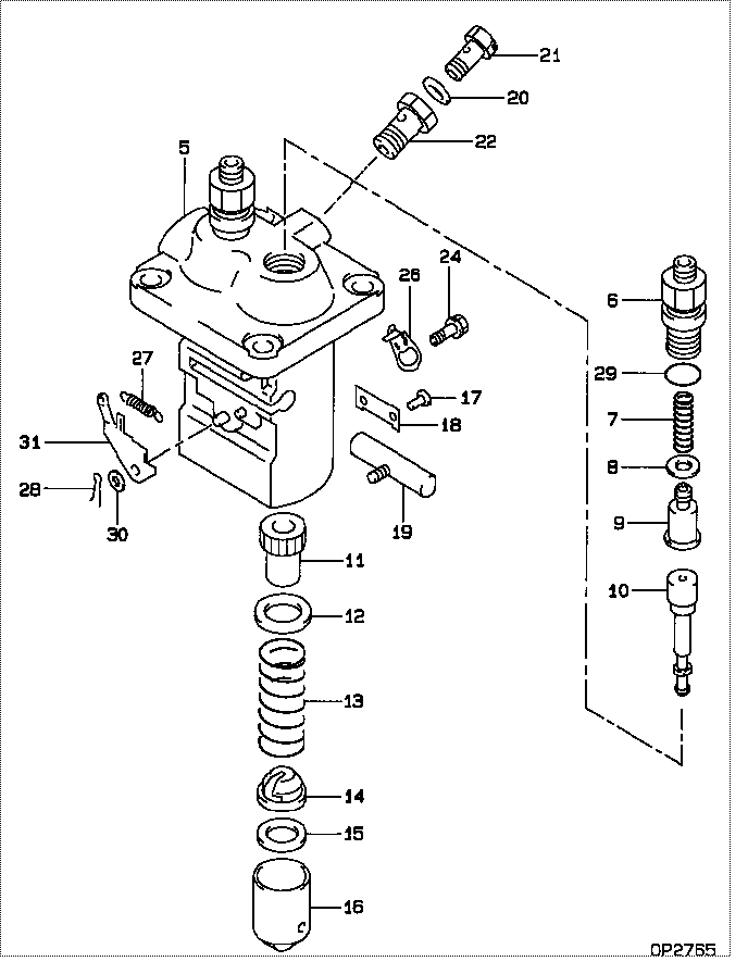
5. Disassemble the fuel injection pump. Remove ring (6). Make a separation of bonnet (5) from the plunger and barrel assembly (7).
Do not remove the gear from the plunger. The gear and plunger are assembled and adjusted at the factory.
6. Remove the plunger and gear segment, washer and spring from the barrel.7. Remove the ring, spring, collar and valve from the barrel. 8. Remove spacer (8) from the pump bore.Install Fuel Injection Pumps
Make sure the fuel racks are in the center (zero) position before the fuel injection pumps are installed. 1. Put plunger (10), washer (5) and spring (9) in position on barrel (4). Put check valve assembly (7), spring (3) and collar (8) in position in bonnet (6). Connect bonnet (6) and barrel (4) together with ring (2). Keep seal (1) with bonnet for use at installation. 2. Put spacer (13) into position in the pump housing bore. Make sure the correct spacer is with each pump.3. Put the space in gear segment (11) in alignment with the groove in barrel (4). 4. Put the injection pump straight down into the housing bore so the space in gear segment (11) is in alignment with pin (12) and the groove in barrel (4) is in alignment with dowel (14). Use Tool (C) to install the pump. 5. Install the seal and bushing (15) in the pump housing bore. If the pump is in the correct position, bushing (15) will turn into the threads of the pump housing with the fingers until it is even with the housing. Tighten bushing (15) to a torque of 205 14 Nm (150 10 lb ft) with Tool (B).6. Install washers (16).7. Connect the fuel lines to the injection pumps and tighten fuel line nuts to a torque of 40 7 Nm (30 5 lb ft) with Tool (D).8. Check for correct installation of the injection pumps with the engine stopped. See the topic "Installation of Injection Pump" in the Systems Operation
When injection pumps, spacers and lifters are removed from the injection pump housing, keep the parts of each pump together so they can be installed back in their original location.
4. Remove fuel injection pump with Tool (C).
Be careful when the injection pumps are disassembled. Do not cause damage to the surface on the plunger. The plunger and barrel for each pump are made as a set. Do not put the plunger of one pump in the barrel of another pump. If one part has wear install a complete new pump assembly. Be careful when the plunger is put into the bore of the barrel.
5. Disassemble the fuel injection pump. Remove ring (6). Make a separation of bonnet (5) from the plunger and barrel assembly (7).
Do not remove the gear from the plunger. The gear and plunger are assembled and adjusted at the factory.
6. Remove the plunger and gear segment, washer and spring from the barrel.7. Remove the ring, spring, collar and valve from the barrel. 8. Remove spacer (8) from the pump bore.Install Fuel Injection Pumps
Make sure the fuel racks are in the center (zero) position before the fuel injection pumps are installed. 1. Put plunger (10), washer (5) and spring (9) in position on barrel (4). Put check valve assembly (7), spring (3) and collar (8) in position in bonnet (6). Connect bonnet (6) and barrel (4) together with ring (2). Keep seal (1) with bonnet for use at installation. 2. Put spacer (13) into position in the pump housing bore. Make sure the correct spacer is with each pump.3. Put the space in gear segment (11) in alignment with the groove in barrel (4). 4. Put the injection pump straight down into the housing bore so the space in gear segment (11) is in alignment with pin (12) and the groove in barrel (4) is in alignment with dowel (14). Use Tool (C) to install the pump. 5. Install the seal and bushing (15) in the pump housing bore. If the pump is in the correct position, bushing (15) will turn into the threads of the pump housing with the fingers until it is even with the housing. Tighten bushing (15) to a torque of 205 14 Nm (150 10 lb ft) with Tool (B).6. Install washers (16).7. Connect the fuel lines to the injection pumps and tighten fuel line nuts to a torque of 40 7 Nm (30 5 lb ft) with Tool (D).8. Check for correct installation of the injection pumps with the engine stopped. See the topic "Installation of Injection Pump" in the Systems Operation