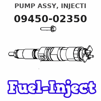
Information pump assy, injecti
Nozzle:
0935001560
Rating:
Components :
| 001. | PUMP ASSY, INJECTI | 09450-02350 |
Scheme ###:
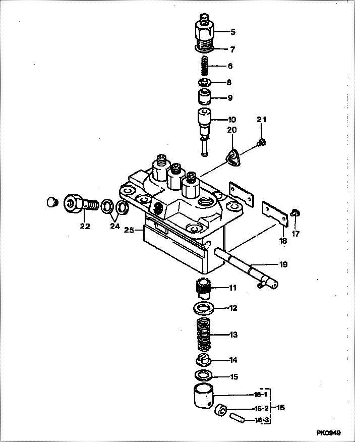
| 000. | [01] | 09450-02350 | PUMP ASSY, INJECTI | 15478-51012 |
| 005. | [04] | 09013-10280 | HOLDER, DELIVERY V | 15601-51221 |
| 005. | [04] | 09013-10520 | HOLDER, DELIVERY V | |
| 006. | [04] | 09013-60230 | SPRING, DELIVERY V | 15221-51231 |
| 007. | [04] | 90802-20150 | O-RING | 14611-51201 |
| 007. | [04] | 09013-90410 | O-RING | |
| 008. | [04] | 09013-70061 | GASKET, DELIVERY V | 15221-51241 |
| 008. | [04] | 09013-70130 | GASKET, DELIVERY V | 11420-51241 |
| 009. | [04] | 09014-00410 | VALVE SUB-ASSY, IN | 15221-51031 |
| 010. | [04] | 09015-01161 | ELEMENT SUB-ASSY, | 15221-51051 |
| 011. | [04] | 09016-10210 | SLEEVE, PLUNGER CO | 15221-51382 |
| 012. | [04] | 09016-30082 | SEAT, SPRING, UPR | 15221-51271 |
| 013. | [01] | 09016-40170 | SPRING, PUMP PLUNG | 15221-51281 |
| 014. | [04] | 09030-10060 | SEAT, SPRING, LWR | 15021-51291 |
| 015. | [ C] | 09031-10310 | PLATE, TAPPET ADJU | |
| 015. | [ C] | 09031-10300 | PLATE, TAPPET ADJU | |
| 015. | [ C] | 09031-10280 | PLATE, TAPPET ADJU | |
| 015. | [ C] | 09031-10170 | PLATE, TAPPET ADJU | |
| 015. | [ C] | 09031-10160 | PLATE, TAPPET ADJU | |
| 015. | [ C] | 09031-10140 | PLATE, TAPPET ADJU | |
| 015. | [ C] | 09031-10130 | PLATE, TAPPET ADJU | 15221-51491 |
| 015. | [ C] | 09031-10120 | PLATE, TAPPET ADJU | |
| 015. | [ C] | 09031-10110 | PLATE, TAPPET ADJU | |
| 015. | [ C] | 09031-10010 | PLATE, TAPPET ADJU | 14109-51301 |
| 016. | [04] | 09017-00170 | TAPPET SUB-ASSY,IN | 15221-51071 |
| 016-001. | [04] | 09017-10021 | TAPPET, INJECTION | 15021-51990 |
| 016-002. | [04] | 09017-60010 | PIN, INJECTION PUM | 15101-52251 |
| 016-003. | [04] | 09017-60020 | PIN, INJECTION PUM | 15021-51970 |
| 017. | [04] | 09018-30050 | PIN, INJECTION PUM | 14611-51251 |
| 018. | [02] | 09046-70030 | PLATE | 14611-51441 |
| 019. | [01] | 09021-00251 | RACK ASSY, CONTROL | 15401-51061 |
| 020. | [03] | 09007-00012 | PLATE ASSY, ADJUST | 14611-51391 |
| 020. | [03] | 09006-80020 | PLATE, ADJUSTING | 14384-51391 |
| 021. | [03] | 94904-71980 | BOLT, W/WASHER | 15221-91031 |
| 021. | [03] | 94904-80800 | BOLT, WASHER HEAD | |
| 022. | [01] | 09024-50170 | SCREW, HOLLOW | 15471-51321 |
| 024. | [01] | 09022-20050 | WASHER, FUEL PIPE | 15401-96652 |
| 025. | [01] | 09011-02540 | HOUSING SUB-ASSY, |
Include in #3:
09450-02350
as PUMP ASSY, INJECTI
Cross reference number
| Part num | Firm num | Firm | Name |
| 09450-02350 | 15478-5101 | PUMP ASSY, INJECTI | |
| 15478-51012 | KUBOTA | PUMP ASSY, INJECTI |
Information:
To prevent damage to the intake and exhaust valves an adjustment must be made to the valve clearance setting. Loosen the nuts on each rocker arm, and move the adjustment screw on each rocker arm away from the bridge as far as possible.
1. Put the engine in position on Tooling (A). Use Tooling (A) to turn the engine so that the crankshaft is up as shown.2. Remove the breather tube and the air cleaner housing and support from the left side of the engine (as seen from the flywheel end of the engine).3. Turn the engine over on its side. Make sure the blocks that are used as support for the top of the engine are against the cylinder head only and not against the exhaust manifold or valve cover bases. 4. Loosen the nuts that hold each connecting rod bearing cap (1) in position. Turn the crankshaft if necessary to loosen all the nuts. Make sure the nuts are still tight enough to hold the bearing caps in place when the crankshaft is turned. 5. Turn the crankshaft so that "V" mark (2) on the crankshaft gear is in alignment with "V" mark (3) on the idler gear.6. Remove the bearing caps that hold the connecting rods in position against the crankshaft. 7. Remove bearings (4) from each bearing cap. Make sure that each bearing is kept with the bearing cap it is removed from for correct installation purposes. 8. Remove all crankshaft main bearing caps (5).9. Push the pistons are far away as possible from the crankshaft. 10. Remove bearing (6) from each crankshaft main bearing cap. Make sure that each bearing is kept with the crankshaft main bearing cap it is removed from for correct installation purposes. 11. Remove two thrust plates (7) from the center main bearings. 12. Fasten Tooling (B) and a hoist to the crankshaft as shown.13. Use Tooling (B) and a hoist to remove crankshaft (8) from the cylinder block. The weight of the crankshaft is approximately 131 kg (290 lb). Lift the crankshaft slowly so the main bearing upper halves stay in the cylinder block. 14. Use Tool (C) to remove gear (9) from the crankshaft. Use Tooling (D) to remove the dowel that is under the gear if a replacement of the dowel is necessary. 15. Use Tooling (E) to remove pin (10) from the crankshaft if a replacement of the pin is necessary. 16. Put identification on main bearing upper halves (11) and connecting rod bearing upper halves (12) as to their location in the cylinder block and connecting rods. Remove bearings (11) and (12).17. Check the condition of the main bearings and crankshaft. Make reference to Guideline For Reusable Parts: Main & Connecting Rod Bearings, SEBF8009 and Visual Inspection of Crankshafts, SEBF8043.Install Crankshaft
If the crankshaft journals and bores for the block and rods were measured at disassembly and found to be within specifications, no further checks are necessary. However, if the serviceman still wants to measure the