Information pump assy, injecti
Nozzle:
0935001660
Rating:
Components :
| 001. | PUMP ASSY, INJECTI | 09450-02310 |
Scheme ###:
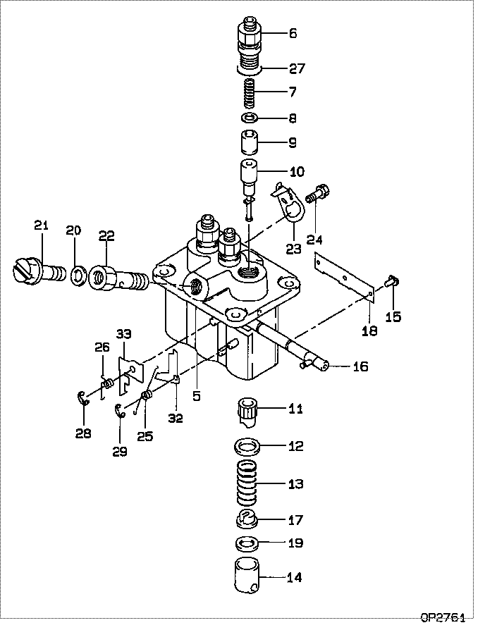
| 000. | [01] | 09450-02310 | PUMP ASSY, INJECTI | MM409274 |
| 005. | [01] | 09011-02590 | HOUSING SUB-ASSY, | MM501312 |
| 006. | [03] | 09013-10280 | HOLDER, DELIVERY V | MM501075 |
| 006. | [03] | 09013-10520 | HOLDER, DELIVERY V | MM501507 |
| 007. | [03] | 09013-60540 | SPRING, DELIVERY V | MM501161 |
| 008. | [03] | 09013-70130 | GASKET, DELIVERY V | MM501856 |
| 008. | [03] | 09013-70061 | GASKET, DELIVERY V | P720-16141 |
| 009. | [03] | 09014-00790 | VALVE SUB-ASSY, IN | MM501046 |
| 010. | [03] | 09015-02860 | ELEMENT SUB-ASSY, | MM501384 |
| 011. | [03] | 09016-10210 | SLEEVE, PLUNGER CO | MM500229 |
| 012. | [03] | 09016-30082 | SEAT, SPRING, UPR | MM501098 |
| 013. | [03] | 09016-40170 | SPRING, PUMP PLUNG | MM500360 |
| 014. | [03] | 09017-00170 | TAPPET SUB-ASSY,IN | MM500230 |
| 014-001. | [03] | 09017-10022 | TAPPET, INJECTION | |
| 014-002. | [03] | 09217-60010 | ROLLER, FEED PUMP | ME702227 |
| 014-003. | [03] | 09017-60020 | PIN, INJECTION PUM | P720-1429 |
| 015. | [03] | 09018-30050 | PIN, INJECTION PUM | MM500231 |
| 016. | [01] | 09021-00470 | RACK ASSY, CONTROL | MM501311 |
| 017. | [03] | 09030-10060 | SEAT, SPRING, LWR | MM500316 |
| 018. | [01] | 09046-70040 | PLATE | MM501162 |
| 019. | [ C] | 09031-10310 | PLATE, TAPPET ADJU | MM501365 |
| 019. | [ C] | 09031-10300 | PLATE, TAPPET ADJU | MM501364 |
| 019. | [ C] | 09031-10280 | PLATE, TAPPET ADJU | MM501246 |
| 019. | [ C] | 09031-10170 | PLATE, TAPPET ADJU | P760-15160 |
| 019. | [ C] | 09031-10160 | PLATE, TAPPET ADJU | MM500314 |
| 019. | [ C] | 09031-10140 | PLATE, TAPPET ADJU | MM500312 |
| 019. | [ C] | 09031-10130 | PLATE, TAPPET ADJU | MM500311 |
| 019. | [ C] | 09031-10120 | PLATE, TAPPET ADJU | MM500310 |
| 019. | [ C] | 09031-10110 | PLATE, TAPPET ADJU | MM500309 |
| 019. | [ C] | 09031-10010 | PLATE, TAPPET ADJU | ME702559 |
| 020. | [01] | 09022-20080 | WASHER, FUEL PIPE | ME702235 |
| 020. | [01] | 94901-81020 | WASHER, COPPER PLA | ME022309 |
| 021. | [01] | 09024-40180 | SCREW, AIR BLEEDER | MM501152 |
| 022. | [01] | 09024-50210 | SCREW, HOLLOW | MM501320 |
| 023. | [02] | 09007-00012 | PLATE ASSY, ADJUST | MM501077 |
| 023. | [02] | 09006-80020 | PLATE, ADJUSTING | MM514109 |
| 024. | [02] | 94904-71980 | BOLT, W/WASHER | MM501244 |
| 024. | [02] | 94904-80800 | BOLT, WASHER HEAD | |
| 025. | [01] | 09055-40300 | SPRING, DIAPHRAGM | MM501256 |
| 026. | [01] | 09055-40170 | SPRING, DIAPHRAGM | MM501074 |
| 027. | [03] | 90802-20150 | O-RING | MM500438 |
| 028. | [01] | 09089-40020 | E-RING | ME702639 |
| 029. | [01] | 09089-40010 | E-RING | ME702112 |
| 032. | [ C] | 09021-92540 | STOPPER | MM501275 |
| 032. | [ C] | 09021-92530 | STOPPER | MM501260 |
| 032. | [ C] | 09021-92520 | STOPPER | MM501259 |
| 032. | [ C] | 09021-92510 | STOPPER | MM501258 |
| 032. | [ C] | 09021-92500 | STOPPER | MM501257 |
| 033. | [ C] | 09021-93740 | STOPPER | |
| 033. | [ C] | 09021-93720 | STOPPER | |
| 033. | [ C] | 09021-93700 | STOPPER | |
| 033. | [ C] | 09021-93680 | STOPPER | MM501272 |
| 033. | [ C] | 09021-93660 | STOPPER | MM501271 |
| 033. | [ C] | 09021-93640 | STOPPER | MM501270 |
| 033. | [ C] | 09021-93620 | STOPPER | MM501269 |
| 033. | [ C] | 09021-93600 | STOPPER | MM501268 |
| 033. | [ C] | 09021-93580 | STOPPER | MM501267 |
| 033. | [ C] | 09021-93760 | STOPPER | MM501386 |
Include in #3:
09450-02310
as PUMP ASSY, INJECTI
Cross reference number
| Part num | Firm num | Firm | Name |
| 09450-02310 | MM409274 | PUMP ASSY, INJECTI | |
| MM409274 | MITSUBISHI | PUMP ASSY, INJECTI |
Information:
3. Remove elbow (1) and fan drive lubricant tube (2).4. Loosen the clamps on hose (7), and move the hose down from cover (5).5. Disconnect cab heater return hose (6) at the valve.6. Mark the location of coolant conditioner hoses (3) and (4), and disconnect them at the fittings. 7. Remove O-ring seal (13) from elbow (11).8. Remove elbow (11) and tube (9).9. Disconnect cab heater supply valve (10) at the fitting.10. Remove four bolts (12) that hold the water pump to the bonnet. Remove O-ring seal (8) from the water pump. 11. Remove four nuts (15) and one bolt that hold water pump (14) to the timing gear housing.12. Remove the water pump and O-ring seal. The following steps are for installation of the water pump.13. Be sure the mating surface of the water pump and timing gear housing is clean.14. Be sure the mating surface of the water pump and bonnet is clean.15. Install a new O-ring seal on water pump (14).16. Install a new gasket between the water pump and the bonnet while installing the water pump on the timing gear housing.17. Install the four nuts and one bolt that hold water pump (14) to the timing gear housing.18. Install four bolts (12) that hold the water pump to the bonnet.19. Connect cab heater supply valve (10) to the fitting.20. Put clean glycerin on the O-ring seals, and install elbow (11) and tube (9). Install a new O-ring seal (13) in the elbow.21. Connect the coolant condition hoses (3) and (4) to the fittings. Connect the hoses in their original location.22. Connect cab heater return hose (6) to the valve.23. Move hose (7) into position on cover (5), and tighten the hose clamps.24. Install elbow (1) with new gaskets, and install fan drive lubricant tube (2).25. Fill the cooling system with coolant to the correct level. See the Maintenance Guide.Disassemble Water Pump
Start By:a. remove water pump 1. Remove O-ring seal (1) from adapter (2).2. Remove adapter (2) with a screwdriver. Remove the seal from the edge of adapter (2).3. Remove bolt (3) and the washer. 4. Remove impeller (4) from the water pump housing with Tooling (A). 5. Remove seal assembly (5). Remove ring and seal (6). 6. Remove the bolt and washer that hold gear (7) on the water pump shaft.7. Remove gear (7) with Tooling (B).8. Remove bolts and retainer (9).9. Remove O-ring seal (8). 10. Remove shaft (10) and the bearings as a unit.11. Remove bearing (11), spacer (12) and bearing (13) from shaft (10).12. Remove the lip-type seal from the gear side of the water pump. Remove the ring and seal from the impeller side of the water pump.13. Use 6V-1541 Quick Cure Primer to clean shaft (10) and the seal counterbore
Start By:a. remove water pump 1. Remove O-ring seal (1) from adapter (2).2. Remove adapter (2) with a screwdriver. Remove the seal from the edge of adapter (2).3. Remove bolt (3) and the washer. 4. Remove impeller (4) from the water pump housing with Tooling (A). 5. Remove seal assembly (5). Remove ring and seal (6). 6. Remove the bolt and washer that hold gear (7) on the water pump shaft.7. Remove gear (7) with Tooling (B).8. Remove bolts and retainer (9).9. Remove O-ring seal (8). 10. Remove shaft (10) and the bearings as a unit.11. Remove bearing (11), spacer (12) and bearing (13) from shaft (10).12. Remove the lip-type seal from the gear side of the water pump. Remove the ring and seal from the impeller side of the water pump.13. Use 6V-1541 Quick Cure Primer to clean shaft (10) and the seal counterbore