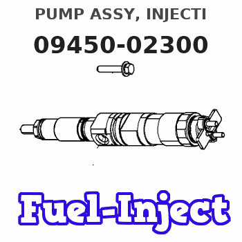
Information pump assy, injecti
Nozzle:
0935001660
Rating:
Components :
| 001. | PUMP ASSY, INJECTI | 09450-02300 |
Scheme ###:
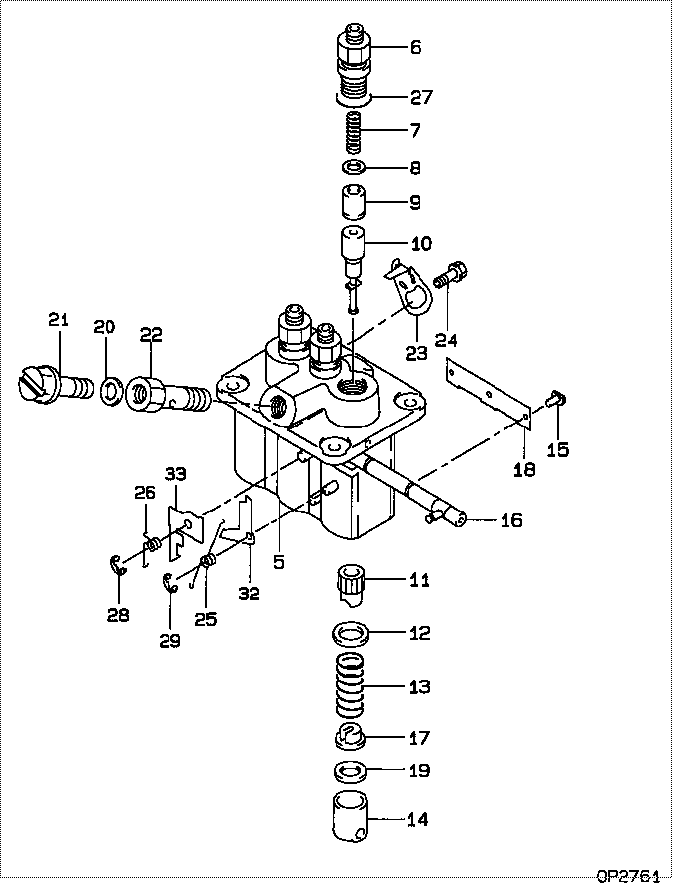
| 000. | [01] | 09450-02300 | PUMP ASSY, INJECTI | MM409273 |
| 005. | [01] | 09011-02590 | HOUSING SUB-ASSY, | MM501312 |
| 006. | [03] | 09013-10280 | HOLDER, DELIVERY V | MM501075 |
| 006. | [03] | 09013-10520 | HOLDER, DELIVERY V | MM501507 |
| 007. | [03] | 09013-60540 | SPRING, DELIVERY V | MM501161 |
| 008. | [03] | 09013-70130 | GASKET, DELIVERY V | MM501856 |
| 008. | [03] | 09013-70061 | GASKET, DELIVERY V | P720-16141 |
| 009. | [03] | 09014-00790 | VALVE SUB-ASSY, IN | MM501046 |
| 010. | [03] | 09015-02860 | ELEMENT SUB-ASSY, | MM501384 |
| 011. | [03] | 09016-10210 | SLEEVE, PLUNGER CO | MM500229 |
| 012. | [03] | 09016-30082 | SEAT, SPRING, UPR | MM501098 |
| 013. | [03] | 09016-40170 | SPRING, PUMP PLUNG | MM500360 |
| 014. | [03] | 09017-00170 | TAPPET SUB-ASSY,IN | MM500230 |
| 014-001. | [03] | 09017-10022 | TAPPET, INJECTION | |
| 014-002. | [03] | 09217-60010 | ROLLER, FEED PUMP | ME702227 |
| 014-003. | [03] | 09017-60020 | PIN, INJECTION PUM | P720-1429 |
| 015. | [03] | 09018-30050 | PIN, INJECTION PUM | MM500231 |
| 016. | [01] | 09021-00470 | RACK ASSY, CONTROL | MM501311 |
| 017. | [03] | 09030-10060 | SEAT, SPRING, LWR | MM500316 |
| 018. | [01] | 09046-70040 | PLATE | MM501162 |
| 019. | [ C] | 09031-10310 | PLATE, TAPPET ADJU | MM501365 |
| 019. | [ C] | 09031-10300 | PLATE, TAPPET ADJU | MM501364 |
| 019. | [ C] | 09031-10280 | PLATE, TAPPET ADJU | MM501246 |
| 019. | [ C] | 09031-10170 | PLATE, TAPPET ADJU | P760-15160 |
| 019. | [ C] | 09031-10160 | PLATE, TAPPET ADJU | MM500314 |
| 019. | [ C] | 09031-10140 | PLATE, TAPPET ADJU | MM500312 |
| 019. | [ C] | 09031-10130 | PLATE, TAPPET ADJU | MM500311 |
| 019. | [ C] | 09031-10120 | PLATE, TAPPET ADJU | MM500310 |
| 019. | [ C] | 09031-10110 | PLATE, TAPPET ADJU | MM500309 |
| 019. | [ C] | 09031-10010 | PLATE, TAPPET ADJU | ME702559 |
| 020. | [01] | 09022-20080 | WASHER, FUEL PIPE | ME702235 |
| 020. | [01] | 94901-81020 | WASHER, COPPER PLA | ME022309 |
| 021. | [01] | 09024-40180 | SCREW, AIR BLEEDER | MM501152 |
| 022. | [01] | 09024-50210 | SCREW, HOLLOW | MM501320 |
| 023. | [02] | 09007-00012 | PLATE ASSY, ADJUST | MM501077 |
| 023. | [02] | 09006-80020 | PLATE, ADJUSTING | MM514109 |
| 024. | [02] | 94904-71980 | BOLT, W/WASHER | MM501244 |
| 024. | [02] | 94904-80800 | BOLT, WASHER HEAD | |
| 025. | [01] | 09055-40300 | SPRING, DIAPHRAGM | MM501256 |
| 026. | [01] | 09055-40170 | SPRING, DIAPHRAGM | MM501074 |
| 027. | [03] | 90802-20150 | O-RING | MM500438 |
| 028. | [01] | 09089-40020 | E-RING | ME702639 |
| 029. | [01] | 09089-40010 | E-RING | ME702112 |
| 032. | [ C] | 09021-92540 | STOPPER | MM501275 |
| 032. | [ C] | 09021-92530 | STOPPER | MM501260 |
| 032. | [ C] | 09021-92520 | STOPPER | MM501259 |
| 032. | [ C] | 09021-92510 | STOPPER | MM501258 |
| 032. | [ C] | 09021-92500 | STOPPER | MM501257 |
| 033. | [ C] | 09021-93700 | STOPPER | |
| 033. | [ C] | 09021-93680 | STOPPER | MM501272 |
| 033. | [ C] | 09021-93660 | STOPPER | MM501271 |
| 033. | [ C] | 09021-93640 | STOPPER | MM501270 |
| 033. | [ C] | 09021-93620 | STOPPER | MM501269 |
| 033. | [ C] | 09021-93600 | STOPPER | MM501268 |
| 033. | [ C] | 09021-93580 | STOPPER | MM501267 |
| 033. | [ C] | 09021-93560 | STOPPER | MM501266 |
| 033. | [ C] | 09021-93540 | STOPPER | MM501265 |
| 033. | [ C] | 09021-93720 | STOPPER |
Include in #3:
09450-02300
as PUMP ASSY, INJECTI
Cross reference number
| Part num | Firm num | Firm | Name |
| 09450-02300 | MM409273 | PUMP ASSY, INJECTI | |
| MM409273 | MITSUBISHI | PUMP ASSY, INJECTI |
Information:
There are two water temperature regulators, one for each cylinder head.1. Drain the coolant from the engine to a level below the water temperature regulators.
Typical Example2. Remove elbow (1). Remove tube and elbow (2). 3. Remove cover assemblies (3). 4. Remove water temperature regulator (4) from each cover assembly. 5. Remove lip-type seal (5) from each cover assembly if a replacement is necessary.6. Check the water temperature regulators. See Specifications Manual SENR6475. The following steps are for the installation of the water temperature regulators. 7. Use Tool (A) to install lip-type seals (5). Install the seals with the lip toward the inside of the covers. Install the seal until it contacts the counterbore in the cover assembly.
If the water temperature regulators are installed incorrectly the engine will over heat.
8. Put clean glycerin on the lip of seal (5), and install water temperature regulator (4) in each cover assembly (3). 9. Install new gaskets (6) and cover assemblies (3).
Typical Example10. Install the gaskets and elbow (1). Put clean engine oil or glycerin on the O-ring seals on tube (2). Install the gasket, tube and elbow (2).11. Fill the cooling system to the correct level. See the Operation & Maintenance Manual.