Information pump assy, injecti
Nozzle:
0935001660
Rating:
Components :
| 001. | PUMP ASSY, INJECTI | 09450-02290 |
Scheme ###:
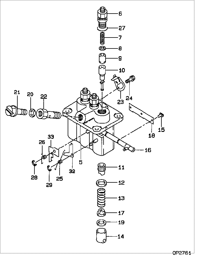
| 000. | [01] | 09450-02290 | PUMP ASSY, INJECTI | MM409266 |
| 005. | [01] | 09011-02590 | HOUSING SUB-ASSY, | MM501312 |
| 006. | [03] | 09013-10280 | HOLDER, DELIVERY V | MM501075 |
| 006. | [03] | 09013-10520 | HOLDER, DELIVERY V | MM501507 |
| 007. | [03] | 09013-60540 | SPRING, DELIVERY V | MM501161 |
| 008. | [03] | 09013-70130 | GASKET, DELIVERY V | MM501856 |
| 008. | [03] | 09013-70061 | GASKET, DELIVERY V | P720-16141 |
| 009. | [03] | 09014-00410 | VALVE SUB-ASSY, IN | MM500227 |
| 010. | [03] | 09015-02120 | ELEMENT SUB-ASSY, | MM501179 |
| 011. | [03] | 09016-10210 | SLEEVE, PLUNGER CO | MM500229 |
| 012. | [03] | 09016-30082 | SEAT, SPRING, UPR | MM501098 |
| 013. | [03] | 09016-40170 | SPRING, PUMP PLUNG | MM500360 |
| 014. | [03] | 09017-00170 | TAPPET SUB-ASSY,IN | MM500230 |
| 014-001. | [03] | 09017-10022 | TAPPET, INJECTION | |
| 014-002. | [03] | 09217-60010 | ROLLER, FEED PUMP | ME702227 |
| 014-003. | [03] | 09017-60020 | PIN, INJECTION PUM | P720-1429 |
| 015. | [03] | 09018-30050 | PIN, INJECTION PUM | MM500231 |
| 016. | [01] | 09021-00470 | RACK ASSY, CONTROL | MM501311 |
| 017. | [03] | 09030-10060 | SEAT, SPRING, LWR | MM500316 |
| 018. | [01] | 09046-70040 | PLATE | MM501162 |
| 019. | [ C] | 09031-10310 | PLATE, TAPPET ADJU | MM501365 |
| 019. | [ C] | 09031-10300 | PLATE, TAPPET ADJU | MM501364 |
| 019. | [ C] | 09031-10280 | PLATE, TAPPET ADJU | MM501246 |
| 019. | [ C] | 09031-10170 | PLATE, TAPPET ADJU | P760-15160 |
| 019. | [ C] | 09031-10160 | PLATE, TAPPET ADJU | MM500314 |
| 019. | [ C] | 09031-10140 | PLATE, TAPPET ADJU | MM500312 |
| 019. | [ C] | 09031-10130 | PLATE, TAPPET ADJU | MM500311 |
| 019. | [ C] | 09031-10120 | PLATE, TAPPET ADJU | MM500310 |
| 019. | [ C] | 09031-10110 | PLATE, TAPPET ADJU | MM500309 |
| 019. | [ C] | 09031-10010 | PLATE, TAPPET ADJU | ME702559 |
| 020. | [01] | 09022-20080 | WASHER, FUEL PIPE | ME702235 |
| 020. | [01] | 94901-81020 | WASHER, COPPER PLA | ME022309 |
| 021. | [01] | 09024-40180 | SCREW, AIR BLEEDER | MM501152 |
| 022. | [01] | 09024-50210 | SCREW, HOLLOW | MM501320 |
| 023. | [02] | 09007-00012 | PLATE ASSY, ADJUST | MM501077 |
| 023. | [02] | 09006-80020 | PLATE, ADJUSTING | MM514109 |
| 024. | [02] | 94904-71980 | BOLT, W/WASHER | MM501244 |
| 024. | [02] | 94904-80800 | BOLT, WASHER HEAD | |
| 025. | [01] | 09055-40300 | SPRING, DIAPHRAGM | MM501256 |
| 026. | [01] | 09055-40160 | SPRING, DIAPHRAGM | MM501073 |
| 027. | [03] | 90802-20150 | O-RING | MM500438 |
| 028. | [01] | 09089-40020 | E-RING | ME702112 |
| 029. | [01] | 09089-40010 | E-RING | ME702112 |
| 032. | [ C] | 09021-92540 | STOPPER | MM501275 |
| 032. | [ C] | 09021-92530 | STOPPER | MM501260 |
| 032. | [ C] | 09021-92520 | STOPPER | MM501259 |
| 032. | [ C] | 09021-92510 | STOPPER | MM501258 |
| 032. | [ C] | 09021-92500 | STOPPER | MM501257 |
| 033. | [ C] | 09021-94110 | STOPPER | MM501353 |
| 033. | [ C] | 09021-94090 | STOPPER | MM501352 |
| 033. | [ C] | 09021-94070 | STOPPER | MM501351 |
| 033. | [ C] | 09021-94050 | STOPPER | MM501350 |
| 033. | [ C] | 09021-94030 | STOPPER | MM501349 |
| 033. | [ C] | 09021-94010 | STOPPER | MM501348 |
| 033. | [ C] | 09021-93990 | STOPPER | MM501347 |
| 033. | [ C] | 09021-93970 | STOPPER | MM501346 |
| 033. | [ C] | 09021-93950 | STOPPER | MM501345 |
| 033. | [ C] | 09021-94130 | STOPPER | MM501354 |
Include in #3:
09450-02290
as PUMP ASSY, INJECTI
Cross reference number
| Part num | Firm num | Firm | Name |
| 09450-02290 | MM409266 | PUMP ASSY, INJECTI | |
| MM409266 | MITSUBISHI | PUMP ASSY, INJECTI |
Information:
Start By:a. remove oil pump 1. Check each main bearing cap (2) for its location on the engine. Each cap has an arrow (1) to show the front of the block and a number (3) which gives the location of that cap.2. Remove No. 2 through No. 4 main bearing caps from the engine. Remove the lower bearings from the caps.3. Remove the thrust plate from each side of the No. 3 upper main bearing.
If the crankshaft is turned in the wrong direction, the tab of the bearing will be pushed between the crankshaft and the cylinder block. This will cause damage to the crankshaft and block.
4. Turn the crankshaft until Tool (A) can be installed in oil hole (4). Turn the crankshaft in the direction which will push the upper main bearing out, tab end first. Install the main bearings dry when clearance checks are made. Put clean engine oil on the main bearings for final assembly.5. Install the lower bearings in the bearing caps.6. Install the upper bearing in the cylinder block with Tool (A). Be sure tab (5) on the back of the bearings fits in the groove of the caps and cylinder block.The serviceman must be very careful to use Plastigage correctly. The following points must be remembered:... Make sure that the backs of the bearings and the bores are clean and dry. ... Make sure that the bearing locking tabs are properly seated in their slots.... The crankshaft must be free of oil where the Plastigage touches it.... Put a piece of Plastigage on the crown of the bearing half that is in the cap. Do not allow the Plastigage to extend over the edge of the bearing.... Install the bearing cap using the correct torque-turn specifications. Do not use an impact wrench. Be careful not to dislodge the bearing when the cap is installed.... Do not turn the crankshaft with the Plastigage installed.... Carefully remove the cap but do not remove the Plastigage. Measure the width of the Plastigage while it is in the bearing cap or on the crankshaft journal. Do this by using the correct scale on the package. Record the measurements.... Remove the Plastigage before reinstalling the cap.When using Plastigage, the readings can sometimes be unclear. For example, all parts of the Plastigage are not the same width. Measure the major widths to make sure that they are within the specification range. Also, experience has shown that when checking clearances tighter than 0.10 mm (.004 in) the readings may be low by 0.013 to 0.025 mm (.0005 to .0010 in). Out-of-round journals can give faulty readings. Also, journal taper may be indicated when one end of the Plastigage is wider that the other.For complete details concerning measuring bearing clearances, see Engine Bearings & Crankshafts, SEBD0531.7. Check the bearing clearance with Tool (B) as follows:
When Plastigage is used to check bearing clearance, do not use an impact wrench for the torque tightening sequence. However, an impact wrench can be used