Information pump assy, injecti
Rating:
Components :
| 001. | PUMP ASSY, INJECTI | 09450-02271 |
Scheme ###:
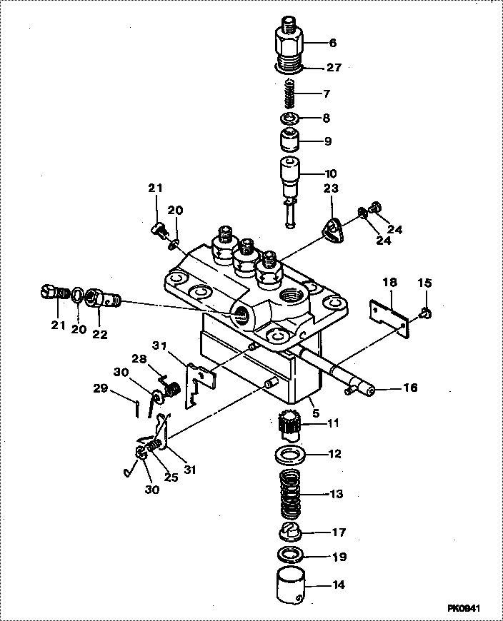
| 000. | [01] | 09450-02271 | PUMP ASSY, INJECTI | MM409851 |
| 005. | [01] | 09011-02420 | HOUSING SUB-ASSY, | MM501253 |
| 006. | [04] | 09013-10280 | HOLDER, DELIVERY V | MM501075 |
| 006. | [04] | 09013-10520 | HOLDER, DELIVERY V | MM501507 |
| 007. | [04] | 09013-60540 | SPRING, DELIVERY V | MM501161 |
| 008. | [04] | 09013-70130 | GASKET, DELIVERY V | MM501856 |
| 008. | [04] | 09013-70061 | GASKET, DELIVERY V | P720-16141 |
| 009. | [04] | 09014-00790 | VALVE SUB-ASSY, IN | MM501046 |
| 010. | [04] | 09015-01531 | ELEMENT SUB-ASSY, | MM501211 |
| 011. | [04] | 09016-10210 | SLEEVE, PLUNGER CO | MM500229 |
| 012. | [04] | 09016-30082 | SEAT, SPRING, UPR | MM501098 |
| 013. | [04] | 09016-40170 | SPRING, PUMP PLUNG | MM500360 |
| 014. | [04] | 09017-00170 | TAPPET SUB-ASSY,IN | MM500230 |
| 014-001. | [04] | 09017-10022 | TAPPET, INJECTION | |
| 014-002. | [04] | 09217-60010 | ROLLER, FEED PUMP | ME702227 |
| 014-003. | [04] | 09017-60020 | PIN, INJECTION PUM | P720-1429 |
| 015. | [04] | 09018-30050 | PIN, INJECTION PUM | MM500231 |
| 016. | [01] | 09021-00440 | RACK ASSY, CONTROL | MM501255 |
| 017. | [04] | 09030-10060 | SEAT, SPRING, LWR | MM500316 |
| 018. | [02] | 09046-70030 | PLATE | MM500232 |
| 019. | [ C] | 09031-10310 | PLATE, TAPPET ADJU | MM501365 |
| 019. | [ C] | 09031-10300 | PLATE, TAPPET ADJU | MM501364 |
| 019. | [ C] | 09031-10280 | PLATE, TAPPET ADJU | MM501246 |
| 019. | [ C] | 09031-10170 | PLATE, TAPPET ADJU | P760-15160 |
| 019. | [ C] | 09031-10160 | PLATE, TAPPET ADJU | MM500314 |
| 019. | [ C] | 09031-10140 | PLATE, TAPPET ADJU | MM500312 |
| 019. | [ C] | 09031-10130 | PLATE, TAPPET ADJU | MM500311 |
| 019. | [ C] | 09031-10120 | PLATE, TAPPET ADJU | MM500310 |
| 019. | [ C] | 09031-10110 | PLATE, TAPPET ADJU | MM500309 |
| 019. | [ C] | 09031-10010 | PLATE, TAPPET ADJU | ME702559 |
| 020. | [01] | 94901-81020 | WASHER, COPPER PLA | ME022309 |
| 021. | [01] | 09314-10170 | NIPPLE, OIL LEAKAG | MM500909 |
| 022. | [01] | 94918-00310 | SCREW, HOLLOW | ME702236 |
| 023. | [03] | 09006-80020 | PLATE, ADJUSTING | MM514109 |
| 023. | [03] | 09007-00012 | PLATE ASSY, ADJUST | MM501077 |
| 024. | [03] | 94904-71980 | BOLT, W/WASHER | MM501244 |
| 024. | [03] | 94904-80800 | BOLT, WASHER HEAD | |
| 025. | [01] | 09055-40300 | SPRING, DIAPHRAGM | MM501256 |
| 026. | [01] | 09055-40160 | SPRING, DIAPHRAGM | MM501073 |
| 027. | [04] | 90802-20150 | O-RING | MM500438 |
| 028. | [01] | 94901-13010 | WASHER, STEEL PLAT | MM500928 |
| 029. | [01] | 90400-16101 | PIN, SPLIT | MM500431 |
| 030. | [01] | 09089-40010 | E-RING | ME702112 |
| 031. | [ C] | 09021-92500 | STOPPER | MM501257 |
| 031. | [ C] | 09021-92510 | STOPPER | MM501258 |
| 031. | [ C] | 09021-92530 | STOPPER | MM501260 |
| 031. | [ C] | 09021-92540 | STOPPER | MM501275 |
| 032. | [ C] | 09021-92810 | STOPPER | |
| 032. | [ C] | 09021-92800 | STOPPER | |
| 032. | [ C] | 09021-92790 | STOPPER | |
| 032. | [ C] | 09021-92780 | STOPPER | |
| 032. | [ C] | 09021-90770 | STOPPER | P760-15570 |
| 032. | [ C] | 09021-92760 | STOPPER | |
| 032. | [ C] | 09021-92750 | STOPPER | |
| 032. | [ C] | 09021-92740 | STOPPER | |
| 032. | [ C] | 09021-92730 | STOPPER | |
| 032. | [ C] | 09021-92820 | STOPPER |
Include in #3:
09450-02271
as PUMP ASSY, INJECTI
Cross reference number
| Part num | Firm num | Firm | Name |
| 09450-02271 | MM409851 | PUMP ASSY, INJECTI |
Information:
Start By:a. remove vibration damper and crankshaft pulley
The crankshaft seal and wear sleeve come as a set and must not be separated from each other at any time. Carefully read Special Instruction, Form No. SMHS8508, that is included with each seal and wear sleeve before any handling of the seal group is made.
1. Use a sharp punch and a hammer to put four equally spaced holes in seal (1).2. Install the tip of Tool (A) into the seal, and use the slide hammer to pull it out of the timing gear housing. Change the location of Tool (A) in the seal in order to pull the seal out evenly. 3. Install 5P-7314 Distorter Ring (3) [part of Tooling (B)] in the space where the seal was removed.
Be careful not to damage the crankshaft surface.
4. Use 5P-7312 Distorter Ring (2) [part of Tooling (B)] to distort the wear sleeve. Put the end of the distorter in the space where the seal was removed.5. Turn the distorter to cause distortion to the wear sleeve. Move the distorter to another position, and turn the distorter again. Do this procedure until the wear sleeve is loose on the crankshaft.6. Remove the distorter, distorter ring and wear sleeve.Install Crankshaft Front Seal & Wear Sleeve
1. Fasten Tooling (A) to the crankshaft.2. Use 6V-1541 Quick Cure Primer to clean the outside diameter of the crankshaft flange and the inside diameter of the wear sleeve.3. Put 9S-3265 Retaining Compound on the outside diameter of the crankshaft flange and the inside diameter of the wear sleeve.
Do not separate the lip-type seal from the wear sleeve. The material in the large lip of the seal can be damaged easily. A scratch or rub (not visible) from a finger can damage the seal enough that it cannot be used. Install the sleeve in the seal. Once there is separation of the sleeve and lip-type seal they cannot be used again and must be replaced with a new seal group. Do not use any type of lubrication during installation of the seal group. If any type of lubrication is used in the installation of the seal group, early seal failure can result.
4. Put seal group (1) in position on Tooling (A). Be sure direction arrows on the seal are the same as crankshaft rotation.5. Put clean engine oil on the face of washer on nut (2) [part of Tooling (B)] that contacts the installer.
The front and rear seals and wear sleeves have different spiral grooves in the seal. Because of this type of design, the front seal group for an engine is different from the rear seal group. If a seal group is installed on the wrong end of the engine, oil can actually be taken out of the engine instead of moving the oil back into the engine.
6. Install Tooling (B) onto Tooling (A), and install nut (2) [part of Tooling (B)] on the threaded shaft of Tooling (A). 7. Tighten nut (2) until Tooling (B) contacts Tooling (A).8.