Information pump assy, injecti
Nozzle:
0935001660
Rating:
Components :
| 001. | PUMP ASSY, INJECTI | 09450-02230 |
Scheme ###:
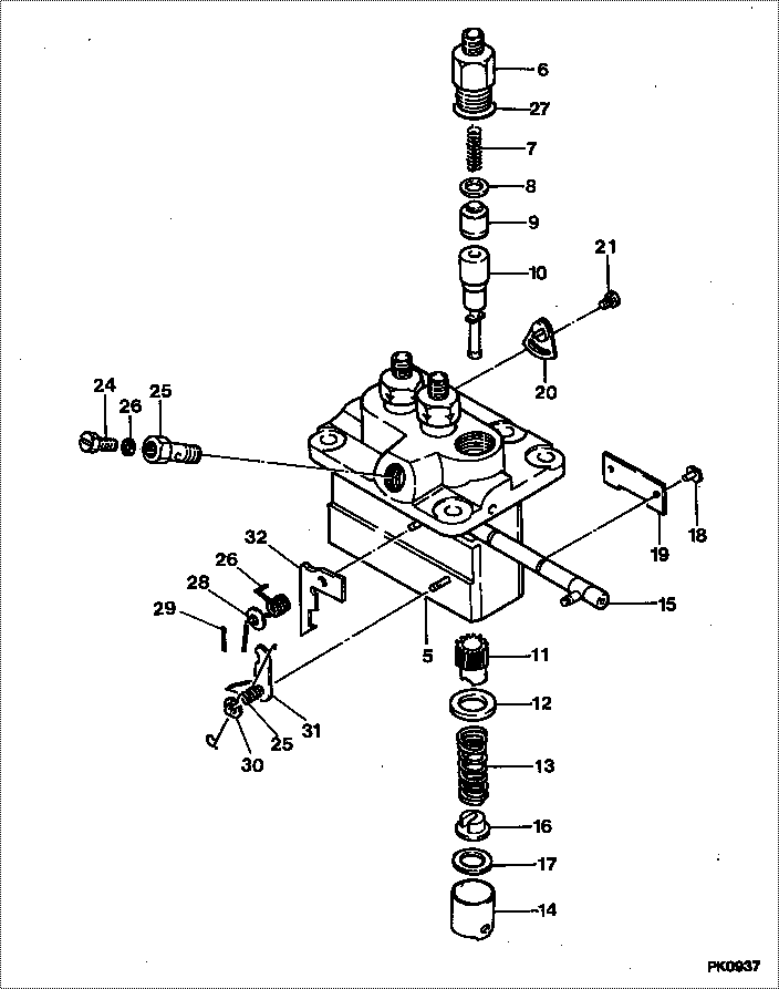
| 000. | [01] | 09450-02230 | PUMP ASSY, INJECTI | MM409268 |
| 005. | [01] | 09011-02590 | HOUSING SUB-ASSY, | MM501312 |
| 006. | [03] | 09013-10280 | HOLDER, DELIVERY V | MM501075 |
| 007. | [03] | 09013-60540 | SPRING, DELIVERY V | MM501161 |
| 008. | [03] | 09013-70061 | GASKET, DELIVERY V | P720-16141 |
| 008. | [03] | 09013-70130 | GASKET, DELIVERY V | MM501856 |
| 009. | [03] | 09014-00790 | VALVE SUB-ASSY, IN | MM501046 |
| 010. | [03] | 09015-02030 | ELEMENT SUB-ASSY, | |
| 011. | [03] | 09016-10210 | SLEEVE, PLUNGER CO | MM500229 |
| 012. | [03] | 09016-30082 | SEAT, SPRING, UPR | MM501098 |
| 013. | [03] | 09016-40170 | SPRING, PUMP PLUNG | MM500360 |
| 014. | [03] | 09017-00170 | TAPPET SUB-ASSY,IN | MM500230 |
| 014-001. | [03] | 09017-10022 | TAPPET, INJECTION | |
| 014-002. | [03] | 09217-60010 | ROLLER, FEED PUMP | ME702227 |
| 014-003. | [03] | 09017-60020 | PIN, INJECTION PUM | P720-1429 |
| 015. | [03] | 09018-30050 | PIN, INJECTION PUM | MM500231 |
| 016. | [01] | 09021-00470 | RACK ASSY, CONTROL | MM501311 |
| 017. | [03] | 09030-10060 | SEAT, SPRING, LWR | MM500316 |
| 018. | [01] | 09046-70040 | PLATE | MM501162 |
| 019. | [ C] | 09031-10310 | PLATE, TAPPET ADJU | MM501365 |
| 019. | [ C] | 09031-10300 | PLATE, TAPPET ADJU | MM501364 |
| 019. | [ C] | 09031-10280 | PLATE, TAPPET ADJU | MM501246 |
| 019. | [ C] | 09031-10170 | PLATE, TAPPET ADJU | P760-15160 |
| 019. | [ C] | 09031-10160 | PLATE, TAPPET ADJU | MM500314 |
| 019. | [ C] | 09031-10140 | PLATE, TAPPET ADJU | MM500312 |
| 019. | [ C] | 09031-10130 | PLATE, TAPPET ADJU | MM500311 |
| 019. | [ C] | 09031-10120 | PLATE, TAPPET ADJU | MM500310 |
| 019. | [ C] | 09031-10110 | PLATE, TAPPET ADJU | MM500309 |
| 019. | [ C] | 09031-10010 | PLATE, TAPPET ADJU | ME702559 |
| 020. | [01] | 09022-20080 | WASHER, FUEL PIPE | ME702235 |
| 021. | [01] | 09024-40150 | SCREW, AIR BLEEDER | |
| 022. | [01] | 09024-50012 | SCREW, HOLLOW | MM500403 |
| 023. | [02] | 09007-00012 | PLATE ASSY, ADJUST | MM501077 |
| 023. | [02] | 09006-80020 | PLATE, ADJUSTING | MM514109 |
| 024. | [02] | 94904-71980 | BOLT, W/WASHER | MM501244 |
| 025. | [01] | 09055-40300 | SPRING, DIAPHRAGM | MM501256 |
| 026. | [01] | 09055-40320 | SPRING, DIAPHRAGM | MM501336 |
| 027. | [03] | 90802-20150 | O-RING | MM500438 |
| 028. | [01] | 94901-13010 | WASHER, STEEL PLAT | MM500928 |
| 029. | [01] | 90400-16101 | PIN, SPLIT | MM500431 |
| 030. | [01] | 09089-40010 | E-RING | ME702112 |
| 031. | [ C] | 09021-92540 | STOPPER | MM501275 |
| 031. | [ C] | 09021-92530 | STOPPER | MM501260 |
| 031. | [ C] | 09021-92520 | STOPPER | MM501259 |
| 031. | [ C] | 09021-92510 | STOPPER | MM501258 |
| 031. | [ C] | 09021-92500 | STOPPER | MM501257 |
| 032. | [ C] | 09021-92810 | STOPPER | |
| 032. | [ C] | 09021-92800 | STOPPER | |
| 032. | [ C] | 09021-92790 | STOPPER | |
| 032. | [ C] | 09021-92780 | STOPPER | |
| 032. | [ C] | 09021-92770 | STOPPER | |
| 032. | [ C] | 09021-92760 | STOPPER | |
| 032. | [ C] | 09021-92750 | STOPPER | |
| 032. | [ C] | 09021-92740 | STOPPER | |
| 032. | [ C] | 09021-92730 | STOPPER | |
| 032. | [ C] | 09021-92720 | STOPPER | |
| 032. | [ C] | 09021-92710 | STOPPER | |
| 032. | [ C] | 09021-92700 | STOPPER | |
| 032. | [ C] | 09021-92690 | STOPPER | |
| 032. | [ C] | 09021-92820 | STOPPER |
Include in #3:
09450-02230
as PUMP ASSY, INJECTI
Cross reference number
| Part num | Firm num | Firm | Name |
| 09450-02230 | MM409268 | PUMP ASSY, INJECTI | |
| MM409268 | MITSUBISHI | PUMP ASSY, INJECTI |
Information:
If fuel line clamps are not installed in their exact location, vibration can cause the fuel lines to break and cause possible personal injury, or damage to the machine.
1. Disconnect front fuel injection lines (1), disconnect middle fuel injection lines (2) and rear fuel injection lines (3) from the fuel injection pump and the cylinder head assembly.2. Remove fuel injection lines (1), (2) and (3). Put caps or plugs on all fuel line connections to keep foreign material out of the fuel system.3. If a separation of the fuel lines has to be made, make sure the exact location of the clamps are marked for assembly purposes. Remove the clamps and make a separation of the fuel lines. The following steps are for the installation of the fuel injection lines.4. Remove the caps or plugs for the fuel injection line connections.5. If removed, connect the fuel lines with the clamps. Make sure the clamps are installed back in their correct location. Use Tool (A) to tighten the clamp bolts to a torque of 2.3 N m (20 lb in). For more information, see Specifications Manual SENR6470, of Testing & Adjusting Manual SENR6471.6. Install front fuel injection lines (1) on the fuel injection pump and cylinder head assembly.7 Install middle fuel injection lines (2) on the fuel injection pump and the cylinder head assembly.8. Install rear fuel injection lines (3) on the fuel injection pump and the cylinder head assembly.9. Tighten the fuel injection line nuts to a torque of 40 7 N m (30 5 lb ft).