Information pump assy, injecti
Nozzle:
0935001660
Rating:
Components :
| 001. | PUMP ASSY, INJECTI | 09450-02180 |
Scheme ###:
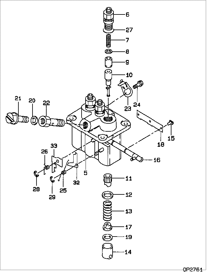
| 000. | [01] | 09450-02180 | PUMP ASSY, INJECTI | MM409264 |
| 005. | [01] | 09011-02590 | HOUSING SUB-ASSY, | MM501312 |
| 006. | [03] | 09013-10280 | HOLDER, DELIVERY V | MM501075 |
| 006. | [03] | 09013-10520 | HOLDER, DELIVERY V | MM501507 |
| 007. | [03] | 09013-60540 | SPRING, DELIVERY V | MM501161 |
| 008. | [03] | 09013-70061 | GASKET, DELIVERY V | P720-16141 |
| 008. | [03] | 09013-70130 | GASKET, DELIVERY V | MM501856 |
| 009. | [03] | 09014-00790 | VALVE SUB-ASSY, IN | MM501046 |
| 010. | [03] | 09015-02110 | ELEMENT SUB-ASSY, | MM501178 |
| 011. | [03] | 09016-10210 | SLEEVE, PLUNGER CO | MM500229 |
| 012. | [03] | 09016-30082 | SEAT, SPRING, UPR | MM501098 |
| 013. | [03] | 09016-40170 | SPRING, PUMP PLUNG | MM500360 |
| 014. | [03] | 09017-00170 | TAPPET SUB-ASSY,IN | MM500230 |
| 014-001. | [03] | 09017-10022 | TAPPET, INJECTION | |
| 014-002. | [03] | 09217-60010 | ROLLER, FEED PUMP | ME702227 |
| 014-003. | [03] | 09017-60020 | PIN, INJECTION PUM | P720-1429 |
| 015. | [03] | 09018-30050 | PIN, INJECTION PUM | MM500231 |
| 016. | [01] | 09021-00470 | RACK ASSY, CONTROL | MM501311 |
| 017. | [03] | 09030-10060 | SEAT, SPRING, LWR | MM500316 |
| 018. | [01] | 09046-70040 | PLATE | MM501162 |
| 019. | [1C] | 09031-10310 | PLATE, TAPPET ADJU | MM501365 |
| 019. | [1C] | 09031-10300 | PLATE, TAPPET ADJU | MM501364 |
| 019. | [1C] | 09031-10280 | PLATE, TAPPET ADJU | MM501246 |
| 019. | [1C] | 09031-10170 | PLATE, TAPPET ADJU | P760-15160 |
| 019. | [1C] | 09031-10160 | PLATE, TAPPET ADJU | MM500314 |
| 019. | [1C] | 09031-10140 | PLATE, TAPPET ADJU | MM500312 |
| 019. | [1C] | 09031-10130 | PLATE, TAPPET ADJU | MM500311 |
| 019. | [1C] | 09031-10120 | PLATE, TAPPET ADJU | MM500310 |
| 019. | [1C] | 09031-10110 | PLATE, TAPPET ADJU | MM500309 |
| 019. | [1C] | 09031-10010 | PLATE, TAPPET ADJU | ME702559 |
| 020. | [01] | 94901-81020 | WASHER, COPPER PLA | ME022309 |
| 020. | [01] | 09022-20080 | WASHER, FUEL PIPE | ME702235 |
| 021. | [01] | 09024-40180 | SCREW, AIR BLEEDER | MM501152 |
| 022. | [01] | 09024-50210 | SCREW, HOLLOW | MM501320 |
| 023. | [02] | 09007-00012 | PLATE ASSY, ADJUST | MM501077 |
| 023. | [02] | 09006-80020 | PLATE, ADJUSTING | MM514109 |
| 024. | [02] | 94904-71980 | BOLT, W/WASHER | MM501244 |
| 024. | [02] | 94904-80800 | BOLT, WASHER HEAD | |
| 025. | [01] | 09055-40300 | SPRING, DIAPHRAGM | MM501256 |
| 026. | [01] | 09055-40160 | SPRING, DIAPHRAGM | MM501073 |
| 027. | [03] | 90802-20150 | O-RING | MM500438 |
| 028. | [01] | 09089-40020 | E-RING | ME702639 |
| 029. | [01] | 09089-40010 | E-RING | ME702112 |
| 032. | [1C] | 09021-92540 | STOPPER | MM501275 |
| 032. | [1C] | 09021-92530 | STOPPER | MM501260 |
| 032. | [1C] | 09021-92520 | STOPPER | MM501259 |
| 032. | [1C] | 09021-92510 | STOPPER | MM501258 |
| 032. | [1C] | 09021-92500 | STOPPER | MM501257 |
| 033. | [1C] | 09021-93720 | STOPPER | |
| 033. | [1C] | 09021-93700 | STOPPER | |
| 033. | [1C] | 09021-93680 | STOPPER | MM501272 |
| 033. | [1C] | 09021-93660 | STOPPER | MM501271 |
| 033. | [1C] | 09021-93640 | STOPPER | MM501270 |
| 033. | [1C] | 09021-93620 | STOPPER | MM501269 |
| 033. | [1C] | 09021-93600 | STOPPER | MM501268 |
| 033. | [1C] | 09021-93580 | STOPPER | MM501267 |
| 033. | [1C] | 09021-93560 | STOPPER | MM501266 |
| 033. | [1C] | 09021-93540 | STOPPER | MM501265 |
| 033. | [1C] | 09021-93520 | STOPPER | MM501264 |
| 033. | [1C] | 09021-93500 | STOPPER | MM501263 |
| 033. | [1C] | 09021-93480 | STOPPER | MM501262 |
| 033. | [1C] | 09021-93740 | STOPPER |
Include in #3:
09450-02180
as PUMP ASSY, INJECTI
Cross reference number
| Part num | Firm num | Firm | Name |
| 09450-02180 | MM409264 | PUMP ASSY, INJECTI | |
| MM409264 | MITSUBISHI | PUMP ASSY, INJECTI |
Information:
2. Turn the crankshaft until two pistons are at bottom center.3. Remove bolts (1) and the bearing caps. Push the rods and pistons up until the rings are out of the cylinder liners. 4. Remove pistons (2) and connecting rods from the cylinder liners.5. Do Steps 1 through 4 for the remainder of the pistons and connecting rods.Install Pistons & Connecting Rod Assemblies
1. Put clean engine oil on piston rings, connecting rod bearings and cylinder liners. 2. Use Tool (A), and install piston (2) and the connecting rod in the cylinder liner.3. Install the bearing cap on the connecting rod with the number on the side of the bearing cap on the same side and same number as on the connecting rod.4. Put 2P2506 Thread Lubricant on the threads of the bolts. Install the nuts, and tighten them to a torque of 90 8 N m (67 6 lb ft). Put a mark on the nuts and cap, and tighten the nuts an extra 90 5 degrees.5. Do Steps 1 through 4 for the remainder of the pistons and connecting rods.End By:a. install piston cooling tubesb. install oil pumpc. install cylinder head assemblyDisassemble & Assemble Pistons & Connecting Rod Assemblies
Start By:a. remove pistons and connecting rod assemblies 1. Remove bearings (3) from the connecting rod and connecting rod cap.2. Remove retainer ring (1) with Tool (A).3. Remove pin (2) and connecting rod (4) from the piston. 4. Remove piston rings (5) from the piston with Tool (B). Clean the piston ring grooves on the pistons with an acceptable ring groove cleaning tool. See, Use Of Piston Bearing Removal And Installation Tools, Special Instructions, SMHS7295.5. Heat connecting rod (4) in an oven to a temperature of 177° to 260°C (350° to 500° F). Never use a direct flame to heat a connecting rod. 6. Put connecting rod (4) in position on the base plate of Tool (C). Put a new rod pin bearing (6) on the adapter part of Tool (C). The old bearing is pushed out by Tool (C) as the new bearing is installed.7. Use Tool (C) to push the new bearing into the connecting rod until the push adapter of Tool (C) makes full contact with the connecting rod surface.8. Use a pin boring machine to make the rod pin bearing the correct size. The bore in the new rod pin bearing must be 50.830 0.008 mm (2.0012 .0003 in).9. Check the clearance between the ends of the piston rings. See the topic, "Pistons & Rings" in Specifications Manual, SENR6470.10. Install the oil ring spring in the oil ring groove of the piston. The oil ring is to be installed over the spring with the oil ring end gap 180° from the oil ring spring joint.11. Install the oil ring on the piston with tool (B).12. Install the second (intermediate) piston ring with the side that has the identification "UP-2" toward the top of the piston. Use Tool (B) to install