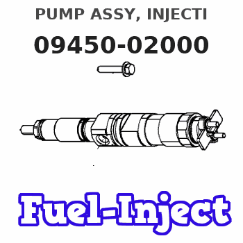
Information pump assy, injecti
Nozzle:
0935002030
Rating:
Components :
| 001. | PUMP ASSY, INJECTI | 09450-02000 |
Scheme ###:
| 000. | [01] | 09450-02000 | PUMP ASSY, INJECTI | EZ40050 |
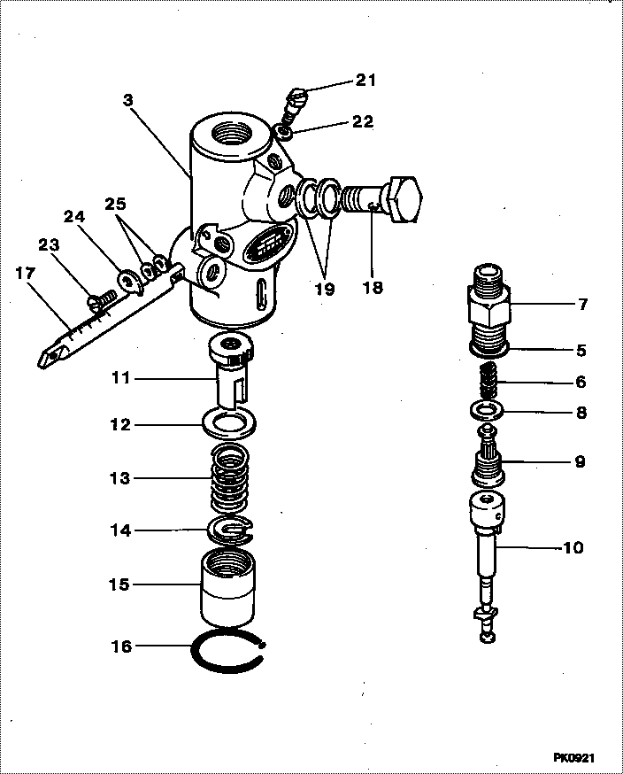
| 003. | [01] | 09011-02520 | HOUSING SUB-ASSY, | |
| 005. | [01] | 94914-02570 | O-RING | 94914-02570 |
| 006. | [01] | 09013-60010 | SPRING, DELIVERY V | 85265-00021 |
| 007. | [01] | 09013-10340 | HOLDER, DELIVERY V | 09013-10340 |
| 008. | [01] | 09013-70100 | GASKET, DELIVERY V | 09013-70100 |
| 009. | [01] | 09014-01170 | VALVE SUB-ASSY, IN | |
| 010. | [01] | 09015-02570 | ELEMENT SUB-ASSY, | |
| 011. | [01] | 09016-10220 | SLEEVE, PLUNGER CO | EZ0066313 |
| 012. | [01] | 09016-30010 | SEAT, SPRING, UPR | 09016-30010 |
| 012. | [01] | 09016-30191 | SEAT, SPRING, UPR | |
| 013. | [01] | 09016-40140 | SPRING, PUMP PLUNG | EZ0096515 |
| 014. | [01] | 09016-50010 | SEAT, SPRING, LWR | 85265-00031 |
| 015. | [01] | 09021-60011 | SLEEVE, GUIDE | EZ0096517 |
| 016. | [01] | 09018-70010 | RING, SNAP | EZ00663018 |
| 017. | [01] | 09021-20320 | RACK, CONTROL | EZ4000303 |
| 018. | [01] | 94918-00310 | SCREW, HOLLOW | 85265-00078 |
| 019. | [02] | 09022-20011 | WASHER, FUEL PIPE | 85265-00048 |
| 019. | [02] | 09022-20070 | WASHER, FUEL PIPE | 85265-00079 |
| 021. | [01] | 09024-40010 | SCREW, AIR BLEEDER | 09024-40010 |
| 022. | [01] | 09024-30030 | PACKING, AIR BLEED | 85265-00016 |
| 023. | [01] | 94904-50150 | BOLT, HEXAGON, W/ | |
| 024. | [01] | 09026-10060 | POINTER | |
| 025. | [ C] | 09026-20010 | WASHER, CONPENSATI | EZ0066327 |
| 025. | [ C] | 09026-30010 | WASHER, CONPENSATI | EZ0066327 |
| 025. | [ C] | 09026-40010 | WASHER, CONPENSATI | EZ0066327 |
| 025. | [ C] | 09026-50010 | WASHER, CONPENSATI | EZ0066327 |
Include in #3:
09450-02000
as PUMP ASSY, INJECTI
Cross reference number
| Part num | Firm num | Firm | Name |
| 09450-02000 | EZ40050 | PUMP ASSY, INJECTI | |
| EZ40050 | MITSUBISHI | PUMP ASSY, INJECTI |
Information:
Start By:a. remove flywheel housing 1. Loosen four bolts (1) approximately 6.4 mm (.25 in). Use Tool (A) to loosen camshaft rear gear (2) from the camshaft.2. Remove Tool (A) and four bolts (1).
If balancer gear (3) is in a position similar to that shown in the picture, the weight on balancer gear (3) will turn down when the camshaft rear gear is removed. To prevent personal injury, hold balancer gear (3) when camshaft rear gear (2) is removed.
3. Remove camshaft rear gear (2). 4. Remove bolt (4), plate (5) and balancer gear (3).5. Inspect the bearing in balancer gear (3). The inside diameter (bore) of a new bearing must be 50.853 to 50.950 mm (2.0021 to 2.0059 in). 6. Use Tooling (B) and a press to remove the bearing from balancer gear (3). 7. Inspect shaft (7) for wear or damage. The outside diameter (new) of shaft (7) must be 50.787 to 50.813 mm (1.9995 to 2.0005 in).8. If a replacement of shaft (7) is necessary, remove bolts (6) and shaft (7) from the cylinder block.Install Camshaft Rear Gear & Balancer
1. Install shaft (7) and four bolts (6) on the cylinder block. 2. Use Tooling (A) to install the bearing in balancer gear (3). Install the bearing so that the bearing joint is on the weight side of the gear within 20 degrees of the centerline as shown. Install the bearing so that it is 1.3 mm (.05 in) from the opposite surface on balancer gear (3). 3. Put clean engine oil on the inside diameter of the bearing in the balancer gear. Install balancer gear (3) and plate (5). Make sure the side of the balancer gear with the weight is toward the cylinder block. Install the bolt (4) that holds the balancer gear in position on the shaft. Check to make sure that there is 0.15 to 0.36 mm (.006 to .014 in) end play between the balancer gear and the shaft.
Be sure the timing "V" marks (8) are aligned when the camshaft rear gear is installed on the camshaft.
4. Engage camshaft rear gear (2) with the dowel on the camshaft. Install bolts (1).5. Tighten bolts (1) to a torque of 23 to 31 N m (17 to 23 lb ft).End By:a. install flywheel housing