Information pump assy, injecti
Nozzle:
0935001660
Rating:
Components :
| 001. | PUMP ASSY, INJECTI | 09450-01960 |
Scheme ###:
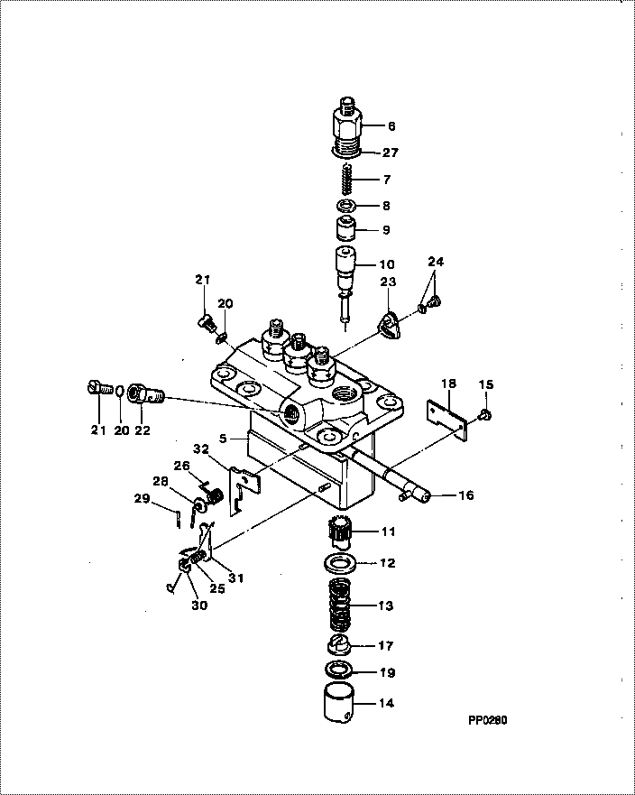
| 000. | [01] | 09450-01960 | PUMP ASSY, INJECTI | MM409023 |
| 005. | [01] | 09011-02420 | HOUSING SUB-ASSY, | MM501253 |
| 006. | [04] | 09013-10520 | HOLDER, DELIVERY V | MM501507 |
| 007. | [04] | 09013-60480 | SPRING, DELIVERY V | MM501047 |
| 008. | [04] | 09013-70130 | GASKET, DELIVERY V | MM501856 |
| 009. | [04] | 09014-00800 | VALVE SUB-ASSY, IN | MM501076 |
| 010. | [04] | 09015-02400 | ELEMENT SUB-ASSY, | MM501254 |
| 011. | [04] | 09016-10210 | SLEEVE, PLUNGER CO | MM500229 |
| 012. | [04] | 09016-30082 | SEAT, SPRING, UPR | MM501098 |
| 013. | [04] | 09016-40170 | SPRING, PUMP PLUNG | MM500360 |
| 014. | [04] | 09017-00170 | TAPPET SUB-ASSY,IN | MM500230 |
| 014-001. | [04] | 09017-10022 | TAPPET, INJECTION | |
| 014-002. | [04] | 09217-60010 | ROLLER, FEED PUMP | ME702227 |
| 014-003. | [04] | 09017-60020 | PIN, INJECTION PUM | P720-1429 |
| 015. | [04] | 09018-30050 | PIN, INJECTION PUM | MM500231 |
| 016. | [01] | 09021-00440 | RACK ASSY, CONTROL | MM501255 |
| 017. | [04] | 09030-10060 | SEAT, SPRING, LWR | MM500316 |
| 018. | [02] | 09046-70030 | PLATE | MM500232 |
| 019. | [4C] | 09031-10310 | PLATE, TAPPET ADJU | MM501365 |
| 019. | [4C] | 09031-10300 | PLATE, TAPPET ADJU | MM501364 |
| 019. | [4C] | 09031-10280 | PLATE, TAPPET ADJU | MM501246 |
| 019. | [4C] | 09031-10170 | PLATE, TAPPET ADJU | P760-15160 |
| 019. | [4C] | 09031-10160 | PLATE, TAPPET ADJU | MM500314 |
| 019. | [4C] | 09031-10140 | PLATE, TAPPET ADJU | MM500312 |
| 019. | [4C] | 09031-10130 | PLATE, TAPPET ADJU | MM500311 |
| 019. | [4C] | 09031-10120 | PLATE, TAPPET ADJU | MM500310 |
| 019. | [4C] | 09031-10110 | PLATE, TAPPET ADJU | MM500309 |
| 019. | [4C] | 09031-10010 | PLATE, TAPPET ADJU | ME702559 |
| 020. | [02] | 94901-81020 | WASHER, COPPER PLA | ME022309 |
| 020. | [02] | 09022-20080 | WASHER, FUEL PIPE | ME702235 |
| 021. | [01] | 09024-40180 | SCREW, AIR BLEEDER | MM501152 |
| 022. | [01] | 94918-00510 | SCREW, HOLLOW | MM500446 |
| 023. | [03] | 09006-80020 | PLATE, ADJUSTING | MM514109 |
| 024. | [03] | 94904-80800 | BOLT, WASHER HEAD | |
| 025. | [01] | 09055-40300 | SPRING, DIAPHRAGM | MM501256 |
| 026. | [01] | 09055-40160 | SPRING, DIAPHRAGM | MM501073 |
| 027. | [04] | 90802-20150 | O-RING | |
| 027. | [04] | 09013-90410 | O-RING | |
| 029. | [01] | 09089-40020 | E-RING | ME702639 |
| 030. | [01] | 09089-40010 | E-RING | ME702112 |
| 032. | [1C] | 09021-93720 | STOPPER | |
| 032. | [1C] | 09021-93700 | STOPPER | |
| 032. | [1C] | 09021-93680 | STOPPER | MM501272 |
| 032. | [1C] | 09021-93660 | STOPPER | MM501271 |
| 032. | [1C] | 09021-93640 | STOPPER | MM501270 |
| 032. | [1C] | 09021-93620 | STOPPER | MM501269 |
| 032. | [1C] | 09021-93600 | STOPPER | MM501268 |
| 032. | [1C] | 09021-93580 | STOPPER | MM501267 |
| 032. | [1C] | 09021-93560 | STOPPER | MM501266 |
| 032. | [1C] | 09021-93540 | STOPPER | MM501265 |
| 032. | [1C] | 09021-92500 | STOPPER | MM501257 |
| 032. | [1C] | 09021-92510 | STOPPER | MM501258 |
| 032. | [1C] | 09021-92520 | STOPPER | MM501259 |
| 032. | [1C] | 09021-92530 | STOPPER | MM501260 |
| 032. | [1C] | 09021-92540 | STOPPER | MM501275 |
| 032. | [1C] | 09021-93480 | STOPPER | MM501262 |
| 032. | [1C] | 09021-93500 | STOPPER | MM501263 |
| 032. | [1C] | 09021-93520 | STOPPER | MM501264 |
| 032. | [1C] | 09021-93740 | STOPPER |
Include in #3:
09450-01960
as PUMP ASSY, INJECTI
Cross reference number
| Part num | Firm num | Firm | Name |
| 09450-01960 | MM409023 | PUMP ASSY, INJECTI | |
| MM409023 | MITSUBISHI | PUMP ASSY, INJECTI |
Information:
1. Disconnect air line (1) at fitting. Remove two bolts (2). Pull up and toward the front of the engine to remove the bolt of the fuel ratio from the groove (slot) in the collar for the governor. Remove fuel ratio control (3). Remove gasket from fuel ratio control.2. Install a new gasket on fuel ratio control. Install fuel ratio control (3). Make sure bolt engages with stop collar in governor control.3. Install two bolts (2). Connect air line (1) at fitting.4. Make sure the fuel ratio control is in correct adjustment. See Systems Operation Testing & Adjusting Manual for this procedure.5. Install a new governor seal.Disassemble Fuel Ratio Control
Start By:a. remove fuel ratio control 1. Remove two bolts (1) and the housing (2). 2. Remove valve assembly (3).3. Remove seal (4) and O-ring seal from valve.4. Remove the retainer (5) and two springs (6). 5. Remove three bolts (9) and cover (10).6. Remove valve (7), diaphragm (8), retainer and spring. 7. Remove pin (12) from valve (7).8. Remove cover (11) from the valve.9. Remove the seal from the cover (11).Assemble Fuel Ratio Control
1. Put clean engine oil on lip of seal. Install the seal (1) in cover (2). Install seal so lip of seal is toward the inside of the cover. 2. Install the valve (3) into cover (2).3. Install the pin that holds cover on valve. 4. Install spring (7) and the retainer (6) in cover (8).5. Install diaphragm (5) on the valve assembly (4) and in the cover. 6. Install cover and three bolts (11) that hold covers together.7. Put clean engine oil on seal and ring seal. Install the seals (10) on valve.8. Install the two springs (13), retainer and valve assembly (12).9. Install housing (9) and two bolts.
Correct adjustment must be made to fuel ratio control before installation. See Systems Operation Testing & Adjusting for this procedure.
End By:a. install fuel ratio control