Information pump assy, injecti
Nozzle:
0935001660
Rating:
Components :
| 001. | PUMP ASSY, INJECTI | 09450-01920 |
Scheme ###:
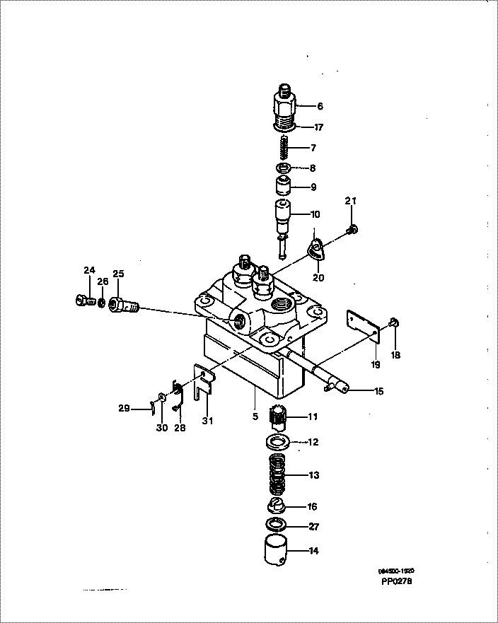
| 000. | [01] | 09450-01920 | PUMP ASSY, INJECTI | MM409003 |
| 005. | [01] | 09011-02090 | HOUSING SUB-ASSY, | MM501159 |
| 006. | [03] | 09013-10520 | HOLDER, DELIVERY V | MM501507 |
| 007. | [03] | 09013-60540 | SPRING, DELIVERY V | MM501161 |
| 008. | [03] | 09013-70130 | GASKET, DELIVERY V | MM501856 |
| 009. | [03] | 09014-00790 | VALVE SUB-ASSY, IN | MM501046 |
| 010. | [03] | 09015-02190 | ELEMENT SUB-ASSY, | MM501200 |
| 011. | [03] | 09016-10210 | SLEEVE, PLUNGER CO | MM500229 |
| 012. | [03] | 09016-30082 | SEAT, SPRING, UPR | MM501098 |
| 013. | [03] | 09016-40170 | SPRING, PUMP PLUNG | MM500360 |
| 014. | [03] | 09017-00170 | TAPPET SUB-ASSY,IN | MM500230 |
| 014-001. | [03] | 09017-10022 | TAPPET, INJECTION | |
| 014-002. | [03] | 09217-60010 | ROLLER, FEED PUMP | ME702227 |
| 014-003. | [03] | 09017-60020 | PIN, INJECTION PUM | P720-1429 |
| 015. | [01] | 09021-00371 | RACK ASSY, CONTROL | MM501160 |
| 016. | [03] | 09030-10060 | SEAT, SPRING, LWR | MM500316 |
| 017. | [03] | 90802-20150 | O-RING | |
| 017. | [03] | 09013-90410 | O-RING | |
| 018. | [03] | 09018-30050 | PIN, INJECTION PUM | MM500231 |
| 019. | [01] | 09046-70040 | PLATE | MM501162 |
| 020. | [02] | 09006-80020 | PLATE, ADJUSTING | MM514109 |
| 021. | [02] | 94904-80800 | BOLT, WASHER HEAD | |
| 024. | [01] | 09024-40180 | SCREW, AIR BLEEDER | MM501152 |
| 025. | [01] | 09024-50210 | SCREW, HOLLOW | MM501320 |
| 026. | [01] | 09022-20080 | WASHER, FUEL PIPE | ME702235 |
| 026. | [01] | 94901-81020 | WASHER, COPPER PLA | ME022309 |
| 027. | [3C] | 09031-10310 | PLATE, TAPPET ADJU | MM501365 |
| 027. | [3C] | 09031-10300 | PLATE, TAPPET ADJU | MM501364 |
| 027. | [3C] | 09031-10280 | PLATE, TAPPET ADJU | MM501246 |
| 027. | [3C] | 09031-10170 | PLATE, TAPPET ADJU | P760-15160 |
| 027. | [3C] | 09031-10160 | PLATE, TAPPET ADJU | MM500314 |
| 027. | [3C] | 09031-10140 | PLATE, TAPPET ADJU | MM500312 |
| 027. | [3C] | 09031-10130 | PLATE, TAPPET ADJU | MM500311 |
| 027. | [3C] | 09031-10120 | PLATE, TAPPET ADJU | MM500310 |
| 027. | [3C] | 09031-10110 | PLATE, TAPPET ADJU | MM500309 |
| 027. | [3C] | 09031-10010 | PLATE, TAPPET ADJU | ME702559 |
| 028. | [01] | 09055-40290 | SPRING, DIAPHRAGM | MM501249 |
| 029. | [01] | 90400-16101 | PIN, SPLIT | MM500431 |
| 029. | [01] | 09089-40020 | E-RING | ME702639 |
| 030. | [01] | 94901-13010 | WASHER, STEEL PLAT | MM500928 |
| 031. | [1C] | 09021-94570 | STOPPER | MM501622 |
| 031. | [1C] | 09021-94560 | STOPPER | |
| 031. | [1C] | 09021-94550 | STOPPER | MM501621 |
| 031. | [1C] | 09021-94540 | STOPPER | MM501620 |
| 031. | [1C] | 09021-94530 | STOPPER | |
| 031. | [1C] | 09021-94520 | STOPPER | MM501619 |
| 031. | [1C] | 09021-94510 | STOPPER | MM501618 |
| 031. | [1C] | 09021-94500 | STOPPER | |
| 031. | [1C] | 09021-94490 | STOPPER | MM501617 |
| 031. | [1C] | 09021-94480 | STOPPER | |
| 031. | [1C] | 09021-94470 | STOPPER | MM501066 |
| 031. | [1C] | 09021-94460 | STOPPER | |
| 031. | [1C] | 09021-94450 | STOPPER | MM501614 |
| 031. | [1C] | 09021-94440 | STOPPER | MM501065 |
| 031. | [1C] | 09021-94580 | STOPPER | MM501623 |
Include in #3:
09450-01920
as PUMP ASSY, INJECTI
Cross reference number
| Part num | Firm num | Firm | Name |
| 09450-01920 | MM409003 | PUMP ASSY, INJECTI | |
| MM409003 | MITSUBISHI | PUMP ASSY, INJECTI |
Information:
Typical Example2. Remove eight bolts (3) that fasten pipe (1) to the elbow. Remove four bolts (2) that fasten the elbow to the aftercooler cover. Remove elbow (4).
Typical Example3. Remove bracket (5) from the oil filter tube and the oil level gauge group.
Typical Example4. Remove four bolts (7) from the air inlet elbow. Remove plate (6) and elbow (8). 5. Remove two tubes (10) from the air compressor to the aftercooler.6. Remove elbows (9) from the aftercooler housing.
Typical Example
Put identification on bolts (12) because they are 6.4 mm (.25 in) longer than all other bolts. They must be installed in the same location.
7. Remove bolts (11) and (12) from cover, and remove the cover.
Put identification on bolt (14) because it is 12.7 mm (.50 in) shorter than all the other bolts. It must be installed in the same location. Remove four adapters (15). Put plugs in both holes in the aftercooler core assembly. This will keep coolant out of the engine intake manifold.
8. Remove bolts (13) and (14) that hold the core assembly in position.9. Remove the aftercooler core assembly. 10. Remove air line (17) from the fuel ratio control valve.11. Remove eight bolts (16). Remove housing assembly (18).Install Aftercooler
1. Check all seals and gaskets for damage. If damaged, use new parts for replacement.
All foreign material and dirt must be removed from the gasket surface and inside the housing and intake manifold.
2. Install housing (1) and air line (2) to the fuel control valve. 3. Install four new seals (3) on the core assembly. Put clean glycerin on the O-ring seals. 4. Install core assembly (4) inside the housing. Remove plugs in both holes of the aftercooler core assembly. Install the bolts that fasten the core to housing. Install the bolts in their original location. 5. Put clean engine oil in the bores of the adapters. Install adapters (5). 6. Put cover (6) in position on the aftercooler. Install the two bolts in position (7). These bolts are 6.4 mm (.25 in) longer than all other bolts around the housing. Install the remainder of the bolts around the housing. 7. Install elbows (8). 8. Install two tubes (9) between the air compressor and the aftercooler.
Typical Example9. Install elbow (10) and plate (11) on the aftercooler cover. Install the bracket that is a support for the oil filter tube and the oil level gauge group. Install the oil filter tube and the oil level gauge group.
Typical Example10. Install eight bolts (13) that fasten the pipe to elbow (14). Install the elbow in the turbocharger.11. Install the four bolts that fasten the elbow to aftercooler cover (12).12. Fill the engine with coolant to the correct level. See the Operation & Maintenance Manual.