Information pump assy, injecti
Nozzle:
0935001660
Rating:
Components :
| 001. | PUMP ASSY, INJECTI | 09450-01780 |
Scheme ###:
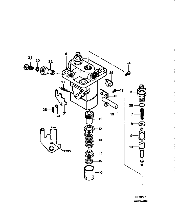
| 000. | [01] | 09450-01780 | PUMP ASSY, INJECTI | MM316933 |
| 005. | [02] | 09013-10520 | HOLDER, DELIVERY V | MM501507 |
| 006. | [01] | 09011-02720 | HOUSING SUB-ASSY, | MM501366 |
| 007. | [02] | 09013-60480 | SPRING, DELIVERY V | MM501047 |
| 008. | [02] | 09013-70130 | GASKET, DELIVERY V | MM501856 |
| 009. | [02] | 09014-00410 | VALVE SUB-ASSY, IN | MM500227 |
| 010. | [02] | 09015-02061 | ELEMENT SUB-ASSY, | MM501176 |
| 011. | [02] | 09016-10210 | SLEEVE, PLUNGER CO | MM500229 |
| 012. | [02] | 09016-30082 | SEAT, SPRING, UPR | MM501098 |
| 013. | [02] | 09016-40170 | SPRING, PUMP PLUNG | MM500360 |
| 014. | [02] | 09030-10060 | SEAT, SPRING, LWR | MM500316 |
| 015. | [2C] | 09031-10310 | PLATE, TAPPET ADJU | MM501365 |
| 015. | [2C] | 09031-10300 | PLATE, TAPPET ADJU | MM501364 |
| 015. | [2C] | 09031-10280 | PLATE, TAPPET ADJU | MM501246 |
| 015. | [2C] | 09031-10170 | PLATE, TAPPET ADJU | P760-15160 |
| 015. | [2C] | 09031-10160 | PLATE, TAPPET ADJU | MM500314 |
| 015. | [2C] | 09031-10140 | PLATE, TAPPET ADJU | MM500312 |
| 015. | [2C] | 09031-10130 | PLATE, TAPPET ADJU | MM500311 |
| 015. | [2C] | 09031-10120 | PLATE, TAPPET ADJU | MM500310 |
| 015. | [2C] | 09031-10110 | PLATE, TAPPET ADJU | MM500309 |
| 015. | [2C] | 09031-10010 | PLATE, TAPPET ADJU | ME702559 |
| 016. | [02] | 09017-00170 | TAPPET SUB-ASSY,IN | MM500230 |
| 016-001. | [02] | 09017-10022 | TAPPET, INJECTION | |
| 016-002. | [02] | 09217-60010 | ROLLER, FEED PUMP | ME702227 |
| 016-003. | [02] | 09017-60020 | PIN, INJECTION PUM | P720-1429 |
| 017. | [02] | 09018-30050 | PIN, INJECTION PUM | MM500231 |
| 018. | [01] | 09046-70030 | PLATE | MM500232 |
| 019. | [01] | 09021-00281 | RACK ASSY, CONTROL | MM500277 |
| 020. | [01] | 94901-81020 | WASHER, COPPER PLA | ME022309 |
| 020. | [01] | 09022-20080 | WASHER, FUEL PIPE | ME702235 |
| 021. | [01] | 09024-40180 | SCREW, AIR BLEEDER | MM501152 |
| 022. | [01] | 09024-50210 | SCREW, HOLLOW | MM501320 |
| 024. | [01] | 94904-80800 | BOLT, WASHER HEAD | |
| 026. | [01] | 09006-80020 | PLATE, ADJUSTING | MM514109 |
| 027. | [01] | 09055-40270 | SPRING, DIAPHRAGM | MM501231 |
| 028. | [01] | 90400-16101 | PIN, SPLIT | MM500431 |
| 029. | [02] | 90802-20150 | O-RING | |
| 029. | [02] | 09013-90410 | O-RING | |
| 030. | [1C] | 94901-34040 | WASHER, PLATE, SK | ME022485 |
| 030. | [1C] | 94901-34030 | WASHER, PLATE, SK | ME022517 |
| 030. | [1C] | 94901-34020 | WASHER, PLATE, SK | ME728059 |
| 030. | [1C] | 94901-33880 | WASHER, PLATE, SK | ME022484 |
| 031. | [1C] | 09021-93400 | STOPPER | MM501558 |
| 031. | [1C] | 09021-93390 | STOPPER | MM501116 |
| 031. | [1C] | 09021-93380 | STOPPER | MM501557 |
| 031. | [1C] | 09021-93370 | STOPPER | MM501115 |
| 031. | [1C] | 09021-93360 | STOPPER | MM501556 |
| 031. | [1C] | 09021-93350 | STOPPER | MM501114 |
| 031. | [1C] | 09021-93340 | STOPPER | MM501555 |
| 031. | [1C] | 09021-93330 | STOPPER | MM501113 |
| 031. | [1C] | 09021-93320 | STOPPER | MM501554 |
| 031. | [1C] | 09021-93310 | STOPPER | MM501112 |
| 031. | [1C] | 09021-93300 | STOPPER | MM501553 |
| 031. | [1C] | 09021-93290 | STOPPER | MM501111 |
| 031. | [1C] | 09021-93280 | STOPPER | MM501552 |
| 031. | [1C] | 09021-93270 | STOPPER | MM501110 |
| 031. | [1C] | 09021-93410 | STOPPER | MM501117 |
Include in #3:
09450-01780
as PUMP ASSY, INJECTI
Cross reference number
| Part num | Firm num | Firm | Name |
| 09450-01780 | MM316933 | PUMP ASSY, INJECTI | |
| MM316933 | MITSUBISHI | PUMP ASSY, INJECTI |
Information:
Start By:a. remove fuel injection lines 1. Remove bolt (1) and clamp (2) from the fuel injection nozzles to be removed.2. Install Tool (A) with the inside lip of the puller on the lower stepped diameter of the nozzle and the tip of the button in the threaded hole for bolt (1).
Do not exceed a torque of 17 N m (150 lb in) on the screw of Tool (A) during removal of the nozzle. Added force can cause the stem of the nozzle to bend or break off.
3. Tighten the screw of Tool (A) to a maximum torque of 17 N m (150 lb in) to remove fuel injection nozzle (3).4. If the fuel injection nozzle can not be removed with a maximum torque of 17 N m (150 lb in) on the screw of Tool (A), remove Tool (A).
Typical Example5. Remove the protective cap from fuel injection nozzle (3), and install Tool (B) as shown.
Hold Tool (B) so the center line of the tool is in alignment with the centerline of fuel injection nozzle (3). This will prevent distortion of the nozzle which can cause it to bend or break off during removal.
6. Remove the fuel injection nozzle with Tool (B).7. If Tool (B) was used to remove the fuel injection nozzle, replace the nozzle.8. If Tool (A) was used to remove the fuel injection nozzle, remove the carbon dam seal on the end of the nozzle.Install Fuel Injection Nozzle
1. Use Tool (C) to clean the bore for the fuel injection nozzle. Use an open end wrench or tap driver to turn Tool (C).2. Make reference to Special Instruction, Form No. SEHS7292, for the use of Tool (D). Clean the fuel injection nozzle with Tool (D). 3. Install a new seal (4) on fuel injection nozzle (3).4. Put carbon dam seal (5) on the small end of Tool (E). Expand the carbon dam seal by sliding it to the large end. Put Tool (E) against the fuel injection nozzle. Slide carbon dam seal (5) off Tool (E) on to the nozzle. Slide the carbon dam seal into position in the groove on the nozzle as shown. 5. Put fuel injection nozzle (3) in position in the cylinder head. Install clamp (2) and bolt (1) to hold the nozzle in position.End By:a. install fuel injection lines