Information pump assy, injecti
Nozzle:
0935001660
Rating:
Components :
| 001. | PUMP ASSY, INJECTI | 09450-01740 |
Scheme ###:
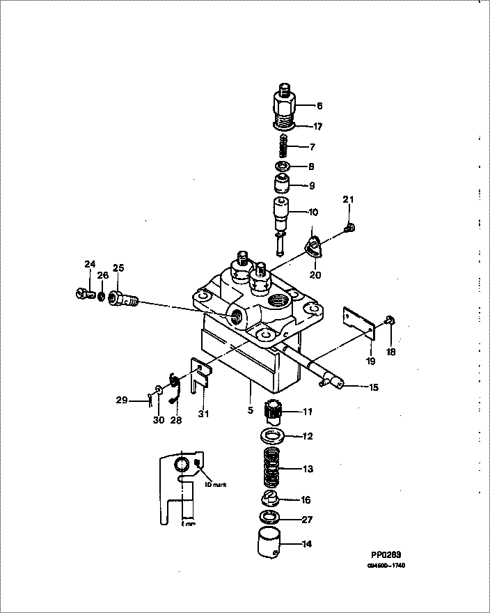
| 000. | [01] | 09450-01740 | PUMP ASSY, INJECTI | MM409013 |
| 005. | [01] | 09011-02090 | HOUSING SUB-ASSY, | MM501159 |
| 006. | [03] | 09013-10520 | HOLDER, DELIVERY V | MM501507 |
| 007. | [03] | 09013-60540 | SPRING, DELIVERY V | MM501161 |
| 008. | [03] | 09013-70130 | GASKET, DELIVERY V | MM501856 |
| 009. | [03] | 09014-00410 | VALVE SUB-ASSY, IN | MM500227 |
| 010. | [03] | 09015-02190 | ELEMENT SUB-ASSY, | MM501200 |
| 011. | [03] | 09016-10210 | SLEEVE, PLUNGER CO | MM500229 |
| 012. | [03] | 09016-30082 | SEAT, SPRING, UPR | MM501098 |
| 013. | [03] | 09016-40170 | SPRING, PUMP PLUNG | MM500360 |
| 014. | [03] | 09017-00170 | TAPPET SUB-ASSY,IN | MM500230 |
| 014-001. | [03] | 09017-10022 | TAPPET, INJECTION | |
| 014-002. | [03] | 09217-60010 | ROLLER, FEED PUMP | ME702227 |
| 014-003. | [03] | 09017-60020 | PIN, INJECTION PUM | P720-1429 |
| 015. | [01] | 09021-00371 | RACK ASSY, CONTROL | MM501160 |
| 016. | [03] | 09030-10060 | SEAT, SPRING, LWR | MM500316 |
| 017. | [03] | 90802-20150 | O-RING | |
| 017. | [03] | 09013-90410 | O-RING | |
| 018. | [03] | 09018-30050 | PIN, INJECTION PUM | MM500231 |
| 019. | [01] | 09046-70040 | PLATE | MM501162 |
| 020. | [02] | 09006-80020 | PLATE, ADJUSTING | MM514109 |
| 021. | [02] | 94904-80800 | BOLT, WASHER HEAD | |
| 024. | [01] | 09024-40180 | SCREW, AIR BLEEDER | MM501152 |
| 025. | [01] | 09024-50210 | SCREW, HOLLOW | MM501320 |
| 026. | [01] | 94901-81020 | WASHER, COPPER PLA | ME022309 |
| 026. | [01] | 09022-20080 | WASHER, FUEL PIPE | ME702235 |
| 027. | [3C] | 09031-10310 | PLATE, TAPPET ADJU | MM501365 |
| 027. | [3C] | 09031-10300 | PLATE, TAPPET ADJU | MM501364 |
| 027. | [3C] | 09031-10280 | PLATE, TAPPET ADJU | MM501246 |
| 027. | [3C] | 09031-10170 | PLATE, TAPPET ADJU | P760-15160 |
| 027. | [3C] | 09031-10160 | PLATE, TAPPET ADJU | MM500314 |
| 027. | [3C] | 09031-10140 | PLATE, TAPPET ADJU | MM500312 |
| 027. | [3C] | 09031-10130 | PLATE, TAPPET ADJU | MM500311 |
| 027. | [3C] | 09031-10120 | PLATE, TAPPET ADJU | MM500310 |
| 027. | [3C] | 09031-10110 | PLATE, TAPPET ADJU | MM500309 |
| 027. | [3C] | 09031-10010 | PLATE, TAPPET ADJU | ME702559 |
| 028. | [01] | 09055-40160 | SPRING, DIAPHRAGM | MM501073 |
| 029. | [01] | 09089-40020 | E-RING | ME702639 |
| 029. | [01] | 90400-16101 | PIN, SPLIT | MM500431 |
| 030. | [01] | 94901-13010 | WASHER, STEEL PLAT | MM500928 |
| 031. | [1C] | 09021-94870 | STOPPER | MM501228 |
| 031. | [1C] | 09021-94840 | STOPPER | MM501227 |
| 031. | [1C] | 09021-94810 | STOPPER | MM501226 |
| 031. | [1C] | 09021-94780 | STOPPER | MM501225 |
| 031. | [1C] | 09021-94750 | STOPPER | |
| 031. | [1C] | 09021-94720 | STOPPER | |
| 031. | [1C] | 09021-94690 | STOPPER | |
| 031. | [1C] | 09021-92410 | STOPPER | MM501221 |
| 031. | [1C] | 09021-92400 | STOPPER | MM501220 |
| 031. | [1C] | 09021-92390 | STOPPER | MM501219 |
| 031. | [1C] | 09021-94900 | STOPPER | MM501229 |
Include in #3:
09450-01740
as PUMP ASSY, INJECTI
Cross reference number
| Part num | Firm num | Firm | Name |
| 09450-01740 | MM409013 | PUMP ASSY, INJECTI | |
| MM409013 | MITSUBISHI | PUMP ASSY, INJECTI |
Information:
Start By:a. remove rocker shaft assembly and push rodsb. remove exhaust manifoldc. remove air cleaner groupd. remove aftercooler The procedure which follows was done on a 3306 Engine. 1. Remove bolts (1), mounting bracket and pipe assembly (2) and lifting bracket (3) from the cylinder head assembly. 2. Remove temperature sending unit (5) from elbow (4).3. Loosen clamp (6), and remove the bolts that hold elbow (4) to the water pump and cylinder head assembly. Remove the elbow and gaskets from the engine. 4. Install Tool (A) on the cylinder head assembly as shown, and fasten a hoist on it.
Do not set the cylinder head assembly on a flat surface because of possible damage to the fuel injection nozzle tips.
5. Remove all bolts (7) and (8) that hold the cylinder head assembly to the cylinder block. Remove the cylinder head assembly. The weight of the cylinder head assembly (3304) is 64 kg (142 lb). The weight of the cylinder head assembly (3306) is 95 kg (210 lb). 6. Remove head gasket (9), water seals (11) and the O-ring seal from dowel (10). Remove spacer plate (12), the spacer plate gasket and the O-ring seal from dowel (10).Install Cylinder Head Assembly & Spacer Plate
The procedure which follows was done on a 3306 Engine.
When the cylinder head assembly is removed a new spacer plate gasket and a new cylinder head gasket must be installed. Do not use any adhesive or other substances on these gaskets or the surfaces they contact.
1. Thoroughly clean the spacer plate, cylinder head and cylinder block surfaces. If dowel (1) was removed for any reason, install a new dowel until it extends 16.0 0.5 mm (.63 .02 in) from the cylinder block.2. Install the O-ring seal on dowel (1) against the cylinder block. Install spacer plate gasket (2) and spacer plate (3) on the cylinder block.3. Check the cylinder liner projection height. See topic, "Install Cylinder Liners". 4. Install the O-ring seal on top of the spacer plate around dowel (1). Install cylinder head gasket (4) and water seals (5). 5. Install Tool (A) on the cylinder head assembly as shown. Fasten a hoist to it. Put the cylinder head assembly in position on the engine.6. Put 2P2506 Thread Lubricant on all the cylinder head bolts. Install them until they are finger tight. Remove Tool (A) from the engine. 7. Install push rods (6). Make sure they are installed in their original locations. Be sure the push rods are in position in the valve lifters.8. Loosen the adjusting screws on the rocker arms for valve clearance. This will prevent a bend valve or push rod during installation of the rocker shaft assembly.9. Install a new O-ring seal in the rear rocker arm support bracket.10. Put 2P2506 Thread Lubricant on all of the rocker shaft bolts except the one that goes through the rear rocker arm support bracket.11. Put rocker shaft assembly (7) in position on the cylinder head assembly. Make sure the dowels in