Information pump assy, injecti
Nozzle:
0935001660
Rating:
Components :
| 001. | PUMP ASSY, INJECTI | 09450-01710 |
Scheme ###:
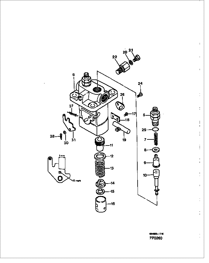
| 000. | [01] | 09450-01710 | PUMP ASSY, INJECTI | MM402939 |
| 005. | [02] | 09013-10520 | HOLDER, DELIVERY V | MM501507 |
| 006. | [01] | 09011-01441 | HOUSING SUB-ASSY, | MM500225 |
| 007. | [02] | 09013-60480 | SPRING, DELIVERY V | MM501047 |
| 008. | [02] | 09013-70130 | GASKET, DELIVERY V | MM501856 |
| 009. | [02] | 09014-00790 | VALVE SUB-ASSY, IN | MM501046 |
| 010. | [02] | 09015-02011 | ELEMENT SUB-ASSY, | MM501154 |
| 011. | [02] | 09016-10210 | SLEEVE, PLUNGER CO | MM500229 |
| 012. | [02] | 09016-30082 | SEAT, SPRING, UPR | MM501098 |
| 013. | [02] | 09016-40170 | SPRING, PUMP PLUNG | MM500360 |
| 014. | [02] | 09030-10060 | SEAT, SPRING, LWR | MM500316 |
| 015. | [2C] | 09031-10310 | PLATE, TAPPET ADJU | MM501365 |
| 015. | [2C] | 09031-10300 | PLATE, TAPPET ADJU | MM501364 |
| 015. | [2C] | 09031-10280 | PLATE, TAPPET ADJU | MM501246 |
| 015. | [2C] | 09031-10170 | PLATE, TAPPET ADJU | P760-15160 |
| 015. | [2C] | 09031-10160 | PLATE, TAPPET ADJU | MM500314 |
| 015. | [2C] | 09031-10140 | PLATE, TAPPET ADJU | MM500312 |
| 015. | [2C] | 09031-10130 | PLATE, TAPPET ADJU | MM500311 |
| 015. | [2C] | 09031-10120 | PLATE, TAPPET ADJU | MM500310 |
| 015. | [2C] | 09031-10110 | PLATE, TAPPET ADJU | MM500309 |
| 015. | [2C] | 09031-10010 | PLATE, TAPPET ADJU | ME702559 |
| 016. | [02] | 09017-00170 | TAPPET SUB-ASSY,IN | MM500230 |
| 016-001. | [02] | 09017-10022 | TAPPET, INJECTION | |
| 016-002. | [02] | 09217-60010 | ROLLER, FEED PUMP | ME702227 |
| 016-003. | [02] | 09017-60020 | PIN, INJECTION PUM | P720-1429 |
| 017. | [02] | 09018-30050 | PIN, INJECTION PUM | MM500231 |
| 018. | [01] | 09046-70030 | PLATE | MM500232 |
| 019. | [01] | 09021-00281 | RACK ASSY, CONTROL | MM500277 |
| 020. | [01] | 94901-81020 | WASHER, COPPER PLA | ME022309 |
| 020. | [01] | 09022-20080 | WASHER, FUEL PIPE | ME702235 |
| 021. | [01] | 09024-40180 | SCREW, AIR BLEEDER | MM501152 |
| 022. | [01] | 09024-50210 | SCREW, HOLLOW | MM501320 |
| 024. | [01] | 94904-80800 | BOLT, WASHER HEAD | |
| 026. | [01] | 09006-80020 | PLATE, ADJUSTING | MM514109 |
| 027. | [01] | 09055-40210 | SPRING, DIAPHRAGM | MM501151 |
| 028. | [01] | 90400-16101 | PIN, SPLIT | MM500431 |
| 029. | [02] | 90802-20150 | O-RING | |
| 029. | [02] | 09013-90410 | O-RING | |
| 030. | [1C] | 94901-34040 | WASHER, PLATE, SK | ME022485 |
| 030. | [1C] | 94901-34030 | WASHER, PLATE, SK | ME022517 |
| 030. | [1C] | 94901-34020 | WASHER, PLATE, SK | ME728059 |
| 030. | [1C] | 94901-33880 | WASHER, PLATE, SK | ME022484 |
| 031. | [1C] | 09021-93350 | STOPPER | MM501114 |
| 031. | [1C] | 09021-93340 | STOPPER | MM501555 |
| 031. | [1C] | 09021-93330 | STOPPER | MM501113 |
| 031. | [1C] | 09021-93320 | STOPPER | MM501554 |
| 031. | [1C] | 09021-93310 | STOPPER | MM501112 |
| 031. | [1C] | 09021-93300 | STOPPER | MM501553 |
| 031. | [1C] | 09021-93290 | STOPPER | MM501111 |
| 031. | [1C] | 09021-93280 | STOPPER | MM501552 |
| 031. | [1C] | 09021-93270 | STOPPER | MM501110 |
| 031. | [1C] | 09021-93260 | STOPPER | MM501551 |
| 031. | [1C] | 09021-93250 | STOPPER | MM501109 |
| 031. | [1C] | 09021-93240 | STOPPER | MM501550 |
| 031. | [1C] | 09021-93230 | STOPPER | MM501108 |
| 031. | [1C] | 09021-93220 | STOPPER | MM501549 |
| 031. | [1C] | 09021-93360 | STOPPER | MM501556 |
Include in #3:
09450-01710
as PUMP ASSY, INJECTI
Cross reference number
| Part num | Firm num | Firm | Name |
| 09450-01710 | MM402939 | PUMP ASSY, INJECTI | |
| MM402939 | MITSUBISHI | PUMP ASSY, INJECTI |
Information:
Start By:a. disassemble governorb. remove fuel injection pumps 1. Remove cover (1) from the fuel injection pump housing. 2. Remove rack (2) from the fuel injection pump housing.
If the original lifters are to be installed in the fuel injection pump housing, put identification marks on them as to their location in the housing.
3. Remove lifters (3) from the fuel injection pump housing. 4. Put the fuel injection pump housing on end on blocks, and use Tool (A) to remove snap ring (4) from the camshaft. 5. Use a soft hammer to push the camshaft toward the governor end of the fuel injection pump housing to loosen washer (5) on the camshaft. Remove washer (5). 6. Remove camshaft (6) from the fuel injection pump housing. 7. Remove bearings (7) from the drive end of the fuel injection pump housing. 8. Remove bearings (8) from the governor end of the fuel injection pump housing.Assemble Fuel Injection Pump Housing
Be sure all oil passages are clear and put clean engine oil on all parts before assembly.1. Use Tool (A) to install bearing (2) in the governor end of the fuel injection pump housing with joint (3) toward the top of the fuel injection pump housing. Install the bearing so it is 0.25 0.20 mm (.010 0.008 in) below the surface of the housing.2. Use Tool (A) to install bearing (1) in the governor end of the fuel injection pump housing so it is 7.16 0.13 mm (0.282 0.005 in) below the surface of the housing. 3. Use Tool (A) to install bearing (4) in the drive end of the fuel injection pump housing with the joint in the bearing toward the top of the fuel injection pump housing. Install the bearing so it is 1.00 0.25 mm (0.039 0.010 in) below the surface of the housing. 4. Install plate assembly (6) of Tool (C) on the drive end of the fuel injection pump housing to install the bearing for the rack. Use clean grease to hold the new rack bearing on driver (5) of Tool (C). Install the driver and bearing in plate assembly (6) with the groove in the driver in alignment with the pin in the plate. Use a hammer to push the bearing into position. The bearing will be installed to the correct depth when the shoulder of the driver is against plate assembly (6).5. Remove Tool (C) from the fuel injection pump housing. The rack bearing must be installed so it is 0.25 0.25 mm (0.010 0.010 in) below the surface of the housing. 6. Install camshaft (7) in the fuel injection pump housing.7. Put the fuel injection pump housing on end, and put a block under the camshaft. 8. Put washer (9) over the end of the camshaft, and use Tool (A) and a spacer (8) that has an inside diameter of 38.1 mm (1.5 in) and a length of 31.75 mm (1.25 in) to push the washer