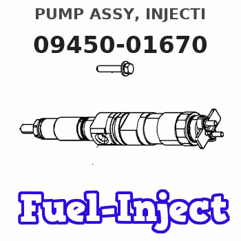
Information pump assy, injecti
Nozzle:
0935001960
Rating:
Components :
| 001. | PUMP ASSY, INJECTI | 09450-01670 |
Scheme ###:
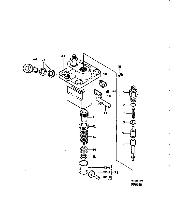
| 000. | [01] | 09450-01670 | PUMP ASSY, INJECTI | 14952-51011 |
| 005. | [02] | 09013-10520 | HOLDER, DELIVERY V | |
| 006. | [02] | 09013-60230 | SPRING, DELIVERY V | 15221-51231 |
| 007. | [02] | 90802-20150 | O-RING | 14611-51201 |
| 008. | [02] | 09013-70130 | GASKET, DELIVERY V | 11420-51241 |
| 009. | [02] | 09014-00410 | VALVE SUB-ASSY, IN | 15221-51031 |
| 010. | [02] | 09015-01790 | ELEMENT SUB-ASSY, | 14911-51051 |
| 011. | [02] | 09016-10210 | SLEEVE, PLUNGER CO | 15221-51382 |
| 012. | [02] | 09016-30082 | SEAT, SPRING, UPR | 15221-51271 |
| 013. | [02] | 09016-40170 | SPRING, PUMP PLUNG | 15221-51281 |
| 014. | [02] | 09030-10060 | SEAT, SPRING, LWR | 15021-51291 |
| 015. | [2C] | 09031-10310 | PLATE, TAPPET ADJU | |
| 015. | [2C] | 09031-10300 | PLATE, TAPPET ADJU | |
| 015. | [2C] | 09031-10280 | PLATE, TAPPET ADJU | |
| 015. | [2C] | 09031-10170 | PLATE, TAPPET ADJU | |
| 015. | [2C] | 09031-10160 | PLATE, TAPPET ADJU | |
| 015. | [2C] | 09031-10140 | PLATE, TAPPET ADJU | |
| 015. | [2C] | 09031-10130 | PLATE, TAPPET ADJU | 15221-51491 |
| 015. | [2C] | 09031-10120 | PLATE, TAPPET ADJU | |
| 015. | [2C] | 09031-10110 | PLATE, TAPPET ADJU | |
| 015. | [2C] | 09031-10010 | PLATE, TAPPET ADJU | 14109-51301 |
| 016. | [01] | 09046-70030 | PLATE | 14611-51441 |
| 017. | [01] | 09021-00290 | RACK ASSY, CONTROL | 15271-51061 |
| 018. | [01] | 09006-80020 | PLATE, ADJUSTING | 14384-51391 |
| 019. | [01] | 94904-80800 | BOLT, WASHER HEAD | |
| 019. | [01] | 94904-71980 | BOLT, W/WASHER | 15221-91031 |
| 020. | [01] | 94918-00610 | SCREW, HOLLOW | 14911-51321 |
| 021. | [02] | 09024-10010 | WASHER, AIR BLEEDE | 15221-96651 |
| 022. | [02] | 09017-00170 | TAPPET SUB-ASSY,IN | 15221-51071 |
| 022-001. | [02] | 09017-10022 | TAPPET, INJECTION | 15021-51990 |
| 022-002. | [02] | 09217-60010 | ROLLER, FEED PUMP | 15109-52931 |
| 022-003. | [02] | 09017-60020 | PIN, INJECTION PUM | 15021-51970 |
| 023. | [02] | 09018-30050 | PIN, INJECTION PUM | 14611-51251 |
| 024. | [01] | 09011-02260 | HOUSING SUB-ASSY, |
Include in #3:
09450-01670
as PUMP ASSY, INJECTI
Cross reference number
| Part num | Firm num | Firm | Name |
| 09450-01670 | 14952-5101 | PUMP ASSY, INJECTI | |
| 14952-51011 | KUBOTA | PUMP ASSY, INJECTI |
Information:
1. Disconnect air line (1) from the fuel ratio control.2. Remove wire seal (4) from the bolts.3. Remove bolts (3) that hold fuel ratio control (2).4. Remove the fuel ratio control by pulling down and out from the collar. The following steps are for the installation of the fuel ratio control.5. Put fuel ratio control (2) in position on the governor. Make sure the valve head of the fuel ratio control is connected in the groove of the collar.6. Install bolts (3) that hold the fuel ratio control to the governor. Connect air line (1) to the fuel ratio control.7. To make an adjustment to the fuel ratio control, see the topic "Governor Adjustment For The Air Fuel Ratio Control" in, Testing & Adjusting Manual SENR6471.8. Install wire seal (4) on the bolts with Tool (A).Disassemble & Assemble Fuel Ratio Control
Start By:a. remove fuel ratio control 1. Put Tool (A) in a vise so that the station being used is not over the vise jaw. Place the fuel ratio control over the pins in Tool (A). Remove bolts (3) and remove cover (26) and gasket (24).
There is spring force behind cover (7). Hold cover (7) in position, and slowly remove the bolts that hold it to release the spring force.
2. Remove bolts (6). Remove cover (7) from housing (10).3. Remove nut (5) and stop (4) from cover (7).4. Remove spring (8), washer (9) and diaphragm (21) from retainer (25). Remove retainer (25) from housing (10).5. Remove tube (1) from the end of extension (19). Remove nut (2) from extension (19) and remove the extension from retainer (25). Remove valve (16), spring (22) and O-ring seal (23) from the extension.6. Remove spring (20), retainer (18) and spring (17) from housing (10).7. Remove piston (12) and valve assembly (14) from the housing.8. Use Tool (B) and remove snap ring (13) and washer (15) from the valve assembly. Remove piston (12) from the valve assembly.9. Remove seal (11) from piston (12).10. If necessary, remove the stem portion from valve assembly (14).11. Clean and inspect all parts. Make a replacement of all parts that are worn and damaged. The following steps are for the assembly of the fuel ratio control.12. If removed during disassembly, assemble the stem portion of valve assembly (14) on the valve using 9S3265 Retaining Compound.13. Lubricate seal (11) lightly with the lubricant being sealed. Put seal (11) on piston (12) and put piston (12) on valve assembly (14).14. Put washer (15) in position on the valve assembly and use Tool (B) to install snap ring (13) on the valve assembly.15. Place housing (10) on Tool (A), and put Tool (C) into the bore of the housing. Lubricate Tool (C) with clean engine oil.16. Push piston (12) into position with a smooth swift motion. Remove Tool (C) from the housing. Place spring (17), retainer (18) and spring (20) in housing (10).17. Put O-ring seal (23) on extension (19). Put spring (22) and valve (16) in position on the