Information pump assy, injecti
Nozzle:
0935001680
Rating:
Components :
| 001. | PUMP ASSY, INJECTI | 09450-01650 |
Scheme ###:
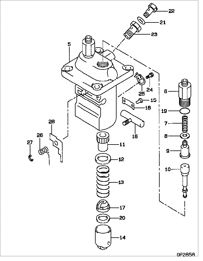
| 000. | [01] | 09450-01650 | PUMP ASSY, INJECTI | MM404926 |
| 005. | [01] | 09011-01592 | HOUSING SUB-ASSY, | MM500981 |
| 006. | [02] | 09013-10350 | HOLDER, DELIVERY V | MM500923 |
| 007. | [02] | 09013-60340 | SPRING, DELIVERY V | MM500925 |
| 008. | [02] | 09013-70130 | GASKET, DELIVERY V | MM501856 |
| 009. | [02] | 09014-00790 | VALVE SUB-ASSY, IN | MM501046 |
| 010. | [02] | 09015-01322 | ELEMENT SUB-ASSY, | MM500936 |
| 011. | [02] | 09016-10110 | SLEEVE, PLUNGER CO | MM500352 |
| 012. | [02] | 09016-30082 | SEAT, SPRING, UPR | MM501098 |
| 013. | [02] | 09016-40041 | SPRING, PUMP PLUNG | EZ01775013 |
| 014. | [02] | 09017-00170 | TAPPET SUB-ASSY,IN | MM500230 |
| 014-001. | [02] | 09017-10022 | TAPPET, INJECTION | |
| 014-002. | [02] | 09017-60020 | PIN, INJECTION PUM | P720-1429 |
| 014-003. | [02] | 09217-60010 | ROLLER, FEED PUMP | ME702227 |
| 015. | [02] | 09018-30050 | PIN, INJECTION PUM | MM500231 |
| 016. | [01] | 09021-00320 | RACK ASSY, CONTROL | MM500930 |
| 017. | [02] | 09030-10060 | SEAT, SPRING, LWR | MM500316 |
| 018. | [01] | 09046-70030 | PLATE | MM500232 |
| 019. | [02] | 09013-90410 | O-RING | |
| 019. | [02] | 90802-20150 | O-RING | |
| 020. | [1C] | 09031-10310 | PLATE, TAPPET ADJU | MM501365 |
| 020. | [1C] | 09031-10300 | PLATE, TAPPET ADJU | MM501364 |
| 020. | [1C] | 09031-10170 | PLATE, TAPPET ADJU | P760-15160 |
| 020. | [1C] | 09031-10160 | PLATE, TAPPET ADJU | MM500314 |
| 020. | [1C] | 09031-10140 | PLATE, TAPPET ADJU | MM500312 |
| 020. | [1C] | 09031-10130 | PLATE, TAPPET ADJU | MM500311 |
| 020. | [1C] | 09031-10120 | PLATE, TAPPET ADJU | MM500310 |
| 020. | [1C] | 09031-10110 | PLATE, TAPPET ADJU | MM500309 |
| 020. | [1C] | 09031-10010 | PLATE, TAPPET ADJU | ME702559 |
| 021. | [01] | 94901-81020 | WASHER, COPPER PLA | ME022309 |
| 021. | [01] | 09022-20080 | WASHER, FUEL PIPE | ME702235 |
| 022. | [01] | 09024-40180 | SCREW, AIR BLEEDER | MM501152 |
| 023. | [01] | 94918-00510 | SCREW, HOLLOW | MM500446 |
| 024. | [01] | 94904-80800 | BOLT, WASHER HEAD | |
| 025. | [01] | 09006-80020 | PLATE, ADJUSTING | MM514109 |
| 026. | [01] | 09055-40120 | SPRING, DIAPHRAGM | MM500929 |
| 027. | [01] | 09089-40020 | E-RING | ME702639 |
| 028. | [1C] | 09021-91781 | STOPPER | MM500920 |
| 028. | [1C] | 09021-91771 | STOPPER | MM500919 |
| 028. | [1C] | 09021-91761 | STOPPER | MM500918 |
| 028. | [1C] | 09021-91751 | STOPPER | MM500917 |
| 028. | [1C] | 09021-91741 | STOPPER | MM500916 |
| 028. | [1C] | 09021-91731 | STOPPER | MM501022 |
| 028. | [1C] | 09021-91721 | STOPPER | MM501021 |
| 028. | [1C] | 09021-91711 | STOPPER | MM501020 |
| 028. | [1C] | 09021-91791 | STOPPER | MM500921 |
Include in #3:
09450-01650
as PUMP ASSY, INJECTI
Cross reference number
| Part num | Firm num | Firm | Name |
| 09450-01650 | MM404926 | PUMP ASSY, INJECTI | |
| MM404926 | MITSUBISHI | PUMP ASSY, INJECTI |
Information:
1. Put the fuel injection pump housing and governor in position on Tool (A).2. Remove the bolts, fuel ratio control (1) and shutoff solenoid (2) from rear governor housing (3).3. Remove the bolts, rear governor housing (3) and the gasket from the front governor housing. 4. Remove governor spring (4), the two wave washers, one flat washer and the seat from the guide in the rear governor housing. 5. Remove bolt (5) that holds lever assembly (6) to the shaft assembly. There is a key in the slot groove of the shaft assembly that must be removed before the shaft assembly is removed from the rear governor housing.6. Remove shaft assembly (7), lever (6) and lever (8) from the rear governor housing. Put an alignment mark on lever (9) for correct assembly purposes.7. Remove bolt (10), lever assembly (9) and spring (11) from shaft assembly (7). 8. Remove plug (12) and lip-type seal (13) from the housing. Spacers (14) and (16) are different sizes. Make sure they are assembled in the correct position.9. Use needle nose pliers, and remove the shaft. Remove spacer (14), lever (15) and spacer (16) from the governor housing. 10. Remove two setscrews and locknuts (17) if necessary. 11. Release spring (18) from the notch in the housing. Remove snap ring (19), and remove shaft (20) from the housing. Remove lever (21) and spring (18). 12. Remove liptype seal (22) from the housing. 13. If necessary, remove the screws, cover (23) and the gasket from the governor housing. 14. Remove high idle cover (24) and three O-ring seals (25). 15. Remove liptype seal (26), dashpot valve (27), fitting (25), insulator and high idle adjustment (28) from the rear housing. 16. Remove two bolts (29), housing (30) and the gasket from the fuel pump housing. 17. Remove bolts (31), and remove torque control group (32) from the block.
Depending on the different engine applications, torque control groups will vary. Inspect all parts for wear and damage, and make a note of the correct sequence of the parts for assembly purposes.
For additional information, see Specifications Manual SENR6470. 18. Remove the bolts and block (33) for the full load stop from the housing. 19. Remove the bolt that holds collar (35) to bolt (36).20. Remove collar (35) and spring (34) from bolt (36). Remove bolt (36) from the block.21. If necessary, remove the stop screw and the power setting screw from collar (35). It may be necessary to turn the piston to remove the servo from the rack.22. Remove the three bolts and governor servo (37) from the fuel injection pump housing. 23. Remove lockring (43), seat (42), spring (41) and sleeve (40) from valve (39). Remove lockring (38) from the groove in the center of valve (39). 24. Remove sleeve (44), valve (45) and piston (46) from the governor servo. Remove O-ring seal (50) from sleeve (44). Do not remove pin (47). If pin (47) and lever (48) or cylinder (49) are worn or damaged replace the