Information pump assy, injecti
Rating:
Components :
| 001. | PUMP ASSY, INJECTI | 09450-01002 |
Scheme ###:
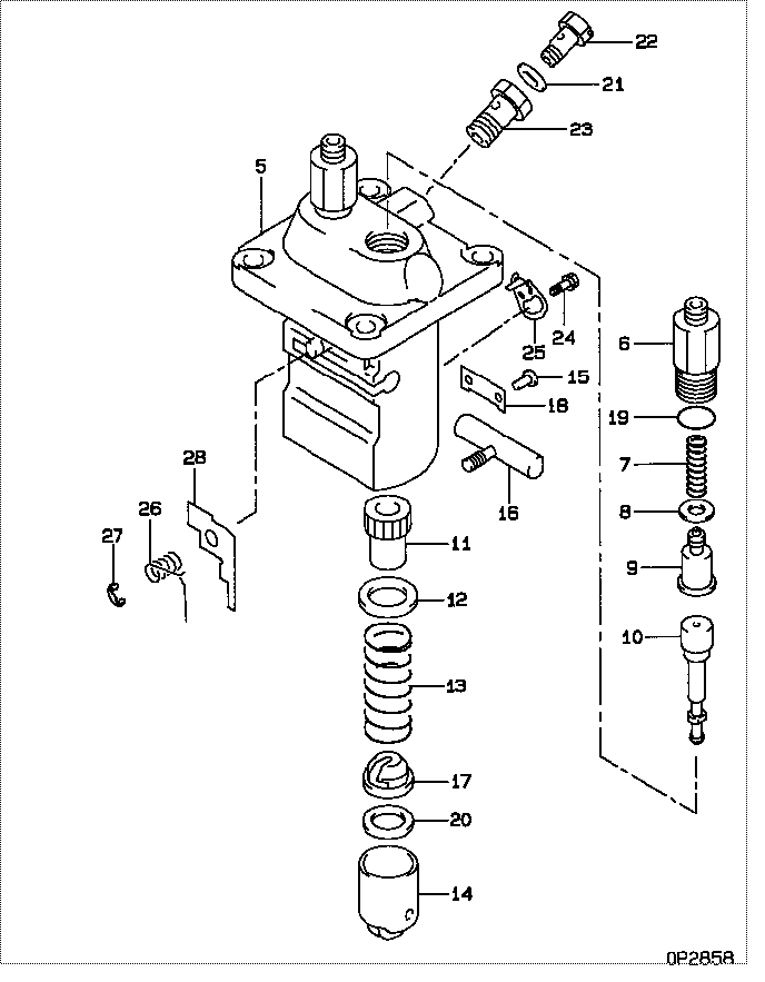
| 000. | [01] | 09450-01002 | PUMP ASSY, INJECTI | MM404940 |
| 005. | [01] | 09011-01592 | HOUSING SUB-ASSY, | MM500981 |
| 006. | [02] | 09013-10350 | HOLDER, DELIVERY V | MM500923 |
| 007. | [02] | 09013-60330 | SPRING, DELIVERY V | MM500924 |
| 008. | [02] | 09013-70130 | GASKET, DELIVERY V | MM501856 |
| 009. | [02] | 09014-00800 | VALVE SUB-ASSY, IN | MM501076 |
| 010. | [02] | 09015-01322 | ELEMENT SUB-ASSY, | MM500936 |
| 011. | [02] | 09016-10110 | SLEEVE, PLUNGER CO | MM500352 |
| 012. | [02] | 09016-30082 | SEAT, SPRING, UPR | MM501098 |
| 013. | [02] | 09016-40041 | SPRING, PUMP PLUNG | EZ01775013 |
| 014. | [02] | 09017-00170 | TAPPET SUB-ASSY,IN | MM500230 |
| 014-001. | [02] | 09017-10022 | TAPPET, INJECTION | |
| 014-002. | [02] | 09017-60020 | PIN, INJECTION PUM | P720-1429 |
| 014-003. | [02] | 09217-60010 | ROLLER, FEED PUMP | ME702227 |
| 015. | [02] | 09018-30050 | PIN, INJECTION PUM | MM500231 |
| 016. | [01] | 09021-00320 | RACK ASSY, CONTROL | MM500930 |
| 017. | [02] | 09030-10060 | SEAT, SPRING, LWR | MM500316 |
| 018. | [01] | 09046-70030 | PLATE | MM500232 |
| 019. | [02] | 09013-90410 | O-RING | |
| 019. | [02] | 90802-20150 | O-RING | |
| 020. | [1C] | 09031-10310 | PLATE, TAPPET ADJU | MM501365 |
| 020. | [1C] | 09031-10300 | PLATE, TAPPET ADJU | MM501364 |
| 020. | [1C] | 09031-10170 | PLATE, TAPPET ADJU | P760-15160 |
| 020. | [1C] | 09031-10160 | PLATE, TAPPET ADJU | MM500314 |
| 020. | [1C] | 09031-10140 | PLATE, TAPPET ADJU | MM500312 |
| 020. | [1C] | 09031-10130 | PLATE, TAPPET ADJU | MM500311 |
| 020. | [1C] | 09031-10120 | PLATE, TAPPET ADJU | MM500310 |
| 020. | [1C] | 09031-10110 | PLATE, TAPPET ADJU | MM500309 |
| 020. | [1C] | 09031-10010 | PLATE, TAPPET ADJU | ME702559 |
| 021. | [01] | 94901-81020 | WASHER, COPPER PLA | ME022309 |
| 021. | [01] | 09022-20080 | WASHER, FUEL PIPE | ME702235 |
| 022. | [01] | 09024-40180 | SCREW, AIR BLEEDER | MM501152 |
| 023. | [01] | 94918-00510 | SCREW, HOLLOW | MM500446 |
| 024. | [01] | 94904-80800 | BOLT, WASHER HEAD | |
| 025. | [01] | 09006-80020 | PLATE, ADJUSTING | MM514109 |
| 026. | [01] | 09055-40120 | SPRING, DIAPHRAGM | MM500929 |
| 027. | [01] | 09089-40020 | E-RING | ME702639 |
| 028. | [1C] | 09021-91721 | STOPPER | MM501021 |
| 028. | [1C] | 09021-91731 | STOPPER | MM501022 |
| 028. | [1C] | 09021-91741 | STOPPER | MM500916 |
| 028. | [1C] | 09021-91751 | STOPPER | MM500917 |
| 028. | [1C] | 09021-91761 | STOPPER | MM500918 |
| 028. | [1C] | 09021-91771 | STOPPER | MM500919 |
| 028. | [1C] | 09021-91781 | STOPPER | MM500920 |
| 028. | [1C] | 09021-91791 | STOPPER | MM500921 |
Include in #3:
09450-01002
as PUMP ASSY, INJECTI
Cross reference number
| Part num | Firm num | Firm | Name |
| 09450-01002 | MM404940 | PUMP ASSY, INJECTI |
Information:
Procedure for Pressure Lubrication
1. Clean the tank of the 1P540 Flow Checking Tool Group thoroughly, and set the pressure regulator to 35 5 psi (240 35 kPa).
Air pressure should not be more than 50 psi (345 kPa) at any time.
2. Put approximately one gallon of engine oil in the tank.
PRESSURE LUBRICATION (Using the 1P540 Flow Checking Tool Group)3. Connect the tools to the engine as shown. The tap shown is connected to the main oil passage.4. Add air pressure to the tank, with the regulator set at 35 5 psi (240 35 kPa). Although the tank does have a hand pump, it is difficult to get enough air pressure to do the job with the hand pump. Therefore, use of shop air is recommended.5. Let the one gallon of engine oil flow into the oil passage under pressure.When filling the crankcase, put in one gallon of oil less than the recommendation in the Lubrication and Maintenance Guides, if engine has received this pressure lubrication application. Also if the engine is not going to be used for a long time, do the above procedure again before the first starting.If shop air is not available for charging the tank, the hand pump may be used to get the minimum required pressure.
Do not use the same 1P540 Flow Checking Tool Group for both "pressure lubrication application" and for checking fuel flow. Incorrect cleaning is probable if the tool is used for both fuel and lube oil. Even a minute amount of dirt in the fuel system can cause fuel nozzle failure.
Dynamometer Test Precaution
To avoid possible engine damage while testing on a dynamometer, the thermostats must be installed and the shunt line connected as shown.
SHUNT LINE CONNECTED TO ENGINEInitial Operation After Engine Reconditioning
The quality of oil control components used in Caterpillar engines is such that, following engine reconditioning (with Caterpillar Service Parts), only an initial operational check is necessary before continued operation in normal service.The purpose of this initial operational check is to: insure that the engine has been assembled properly; determine if proper pressures and temperatures are maintained in the lubrication, cooling and fuel systems; correct any leaks; perform necessary adjustments (such as valve clearance, governor high and low idle speeds, etc.); check the power setting of the engine.To provide a safe, uniform initial operational check, the following procedure is recommended:1. Motor engine at cranking speed until oil pressure is observed.2. Operate engine for 10 minutes at low idle.3. Operate engine for 15 minutes at half-load and 3/4rated speed.4. Operate engine for 30 minutes at rated load and speed.