Information pump assy, injecti
Rating:
Components :
| 001. | PUMP ASSY, INJECTI | 09450-00973 |
Scheme ###:
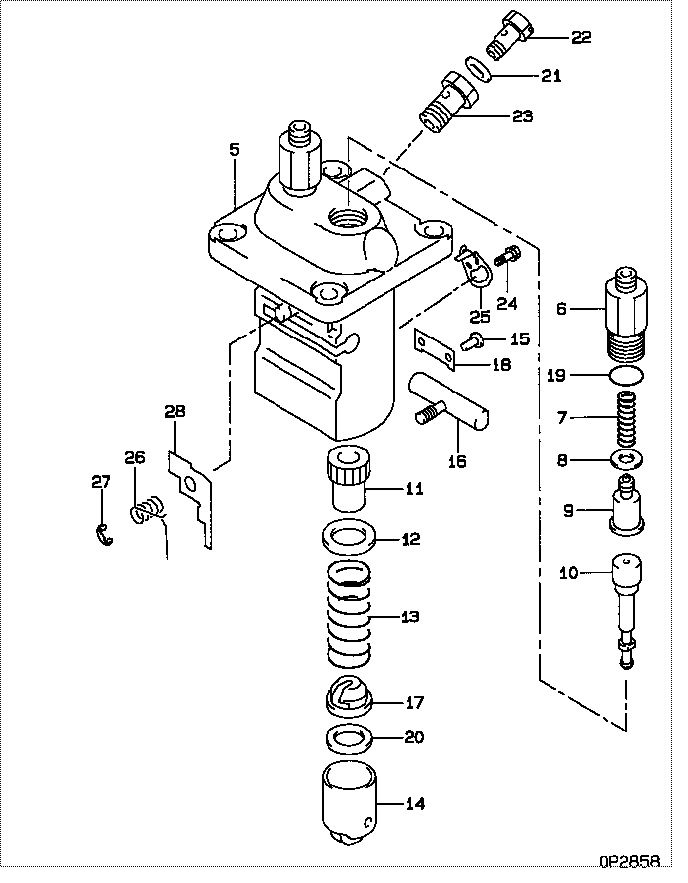
| 000. | [01] | 09450-00973 | PUMP ASSY, INJECTI | MM404923 |
| 005. | [01] | 09011-01592 | HOUSING SUB-ASSY, | MM500981 |
| 006. | [02] | 09013-10350 | HOLDER, DELIVERY V | MM500923 |
| 007. | [02] | 09013-60330 | SPRING, DELIVERY V | MM500924 |
| 008. | [02] | 09013-70130 | GASKET, DELIVERY V | MM501856 |
| 009. | [02] | 09014-00800 | VALVE SUB-ASSY, IN | MM501076 |
| 010. | [02] | 09015-01322 | ELEMENT SUB-ASSY, | MM500936 |
| 011. | [02] | 09016-10110 | SLEEVE, PLUNGER CO | MM500352 |
| 012. | [02] | 09016-30082 | SEAT, SPRING, UPR | MM501098 |
| 013. | [02] | 09016-40041 | SPRING, PUMP PLUNG | EZ01775013 |
| 014. | [02] | 09017-00170 | TAPPET SUB-ASSY,IN | MM500230 |
| 014-001. | [02] | 09017-10022 | TAPPET, INJECTION | |
| 014-002. | [02] | 09017-60020 | PIN, INJECTION PUM | P720-1429 |
| 014-003. | [02] | 09217-60010 | ROLLER, FEED PUMP | ME702227 |
| 015. | [02] | 09018-30050 | PIN, INJECTION PUM | MM500231 |
| 016. | [01] | 09021-00320 | RACK ASSY, CONTROL | MM500930 |
| 017. | [02] | 09030-10060 | SEAT, SPRING, LWR | MM500316 |
| 018. | [01] | 09046-70030 | PLATE | MM500232 |
| 019. | [02] | 09013-90410 | O-RING | |
| 019. | [02] | 90802-20150 | O-RING | |
| 020. | [1C] | 09031-10310 | PLATE, TAPPET ADJU | MM501365 |
| 020. | [1C] | 09031-10300 | PLATE, TAPPET ADJU | MM501364 |
| 020. | [1C] | 09031-10170 | PLATE, TAPPET ADJU | P760-15160 |
| 020. | [1C] | 09031-10160 | PLATE, TAPPET ADJU | MM500314 |
| 020. | [1C] | 09031-10140 | PLATE, TAPPET ADJU | MM500312 |
| 020. | [1C] | 09031-10130 | PLATE, TAPPET ADJU | MM500311 |
| 020. | [1C] | 09031-10120 | PLATE, TAPPET ADJU | MM500310 |
| 020. | [1C] | 09031-10110 | PLATE, TAPPET ADJU | MM500309 |
| 020. | [1C] | 09031-10010 | PLATE, TAPPET ADJU | ME702559 |
| 021. | [01] | 94901-81020 | WASHER, COPPER PLA | ME022309 |
| 021. | [01] | 09022-20080 | WASHER, FUEL PIPE | ME702235 |
| 022. | [01] | 09024-40180 | SCREW, AIR BLEEDER | MM501152 |
| 023. | [01] | 94918-00510 | SCREW, HOLLOW | MM500446 |
| 024. | [01] | 94904-80800 | BOLT, WASHER HEAD | |
| 025. | [01] | 09006-80020 | PLATE, ADJUSTING | MM514109 |
| 026. | [01] | 09055-40130 | SPRING, DIAPHRAGM | MM500950 |
| 027. | [01] | 09089-40020 | E-RING | ME702639 |
| 028. | [1C] | 09021-91731 | STOPPER | MM501022 |
| 028. | [1C] | 09021-91721 | STOPPER | MM501021 |
| 028. | [1C] | 09021-91711 | STOPPER | MM501020 |
| 028. | [1C] | 09021-91701 | STOPPER | MM501019 |
| 028. | [1C] | 09021-91691 | STOPPER | MM501018 |
| 028. | [1C] | 09021-91681 | STOPPER | MM501017 |
| 028. | [1C] | 09021-91671 | STOPPER | MM501016 |
| 028. | [1C] | 09021-91661 | STOPPER | MM501015 |
| 028. | [1C] | 09021-91741 | STOPPER | MM500916 |
Include in #3:
09450-00973
as PUMP ASSY, INJECTI
Cross reference number
| Part num | Firm num | Firm | Name |
| 09450-00973 | MM404923 | PUMP ASSY, INJECTI |
Information:
Engine Design
Cylinder And Valve IdentificationBore ... 120.7 mm (4.75 in)Stroke ... 152.4 mm (6.00 in)Number of Cylinders ... 6Cylinder Arrangement ... in-lineFiring Order (Injection Sequence) ... 1,5,3,6,2,4Direction of Rotation (when seen from flywheel end) ... CounterclockwiseThe No. 1 Cylinder Is Opposite Flywheel End.Fuel System
Fuel Flow
Fuel System Schematic
(1) Fuel tank. (2) Fuel return line. (3) Priming pump. (4) Fuel injection nozzle. (5) Fuel injection line. (6) Fuel injection pump. (7) Primary fuel filter. (8) Check valve. (9) Fuel transfer pump. (10) Secondary fuel filter. (11) Constant bleed orifice. (12) Fuel injection pump housing.Fuel is pulled from fuel tank (1) through primary fuel filter (7) and check valves (8) by fuel transfer pump (9). From the fuel transfer pump the fuel is pushed through secondary fuel filter (10) and to the fuel manifold in fuel injection pump housing (12). The pumping spring in the fuel transfer pump keeps the fuel pressure in the system at 170 to 290 kPa (25 to 42 psi). Constant bleed orifice (11) lets a constant flow of fuel go through fuel return line (2) back to fuel tank (1). This helps keep the fuel cool and free of air. Fuel injection pump (6) gets fuel from the fuel manifold and pushes fuel at very high pressure through fuel line (5) to fuel injection nozzle (4). The fuel injection nozzle has very small holes in the tip that change the flow of fuel to a very fine spray that gives good fuel combustion in the cylinder.Fuel Injection Pump
The fuel injection pump increases the pressure of the fuel and sends an exact amount of fuel to the fuel injection nozzle. There is one fuel injection pump for each cylinder in the engine.The fuel injection pump is moved by cam (12) of the fuel pump camshaft. When the camshaft turns, the cam raises lifter (11) and pump plunger (7) to the top of the stroke. The pump plunger always makes a full stroke. As the camshaft turns farther, spring (8) returns the pump plunger and lifter to the bottom of the stoke.When the pump plunger is at the bottom of the stroke, fuel transfer pump pressure goes into inlet passage (1), around the pump barrel and to bypass closed port (3). Fuel fills the area above the pump plunger.After the pump plunger begins the up stroke, fuel will be pushed out the bypass closed port until the top of the pump plunger closes the port. As the pump plunger travels farther up, the pressure of the fuel increases. At approximately 690 kPa (100 psi), check valve (2) opens and lets fuel flow into the fuel injection line to the fuel injection nozzle. When the pump plunger travels farther up, scroll (5) uncovers spill port (4). The fuel above the pump plunger goes through slot (6), along the edge of scroll (5) and out spill port (4) back to the fuel manifold. This is the end of the injection stroke. The pump plunger can have more travel up,