Information pump assy, injecti
Nozzle:
0935001010
Rating:
Components :
| 001. | PUMP ASSY, INJECTI | 09450-00530 |
Scheme ###:
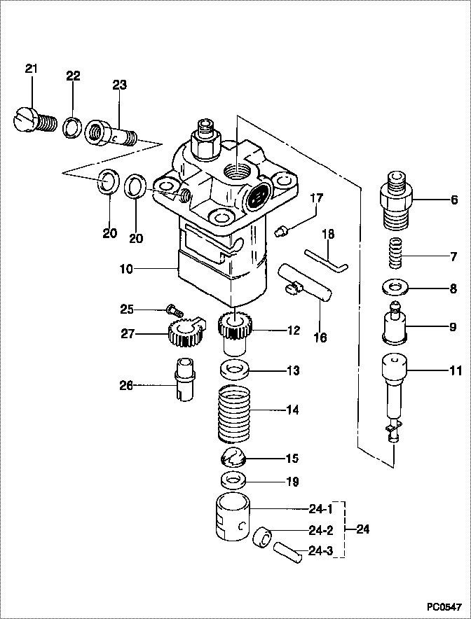
| 000. | [01] | 09450-00530 | PUMP ASSY, INJECTI | 14621-51011 |
| 006. | [02] | 09013-10031 | HOLDER, DELIVERY V | 14109-51221 |
| 007. | [02] | 09013-60150 | SPRING, DELIVERY V | 14412-51231 |
| 008. | [02] | 09013-70020 | GASKET, DELIVERY V | 15021-51241 |
| 009. | [02] | 09014-00030 | VALVE SUB-ASSY, IN | 15021-51031 |
| 010. | [01] | 09011-00801 | HOUSING SUB-ASSY, | |
| 011. | [02] | 09015-01291 | ELEMENT SUB-ASSY, | 14611-51051 |
| 012. | [02] | 09016-10110 | SLEEVE, PLUNGER CO | 14109-51390 |
| 013. | [02] | 09016-30080 | SEAT, SPRING, UPR | 15221-51271 |
| 014. | [02] | 09016-40041 | SPRING, PUMP PLUNG | 14109-51280 |
| 015. | [02] | 09030-10060 | SEAT, SPRING, LWR | 15021-51291 |
| 016. | [01] | 09021-00170 | RACK ASSY, CONTROL | 14412-51061 |
| 017. | [02] | 09018-30010 | PIN, INJECTION PUM | 14109-51250 |
| 018. | [01] | 09018-50010 | PIN, CLAMP | 15021-51431 |
| 019. | [1C] | 09031-10170 | PLATE, TAPPET ADJU | |
| 019. | [1C] | 09031-10160 | PLATE, TAPPET ADJU | |
| 019. | [1C] | 09031-10140 | PLATE, TAPPET ADJU | |
| 019. | [1C] | 09031-10130 | PLATE, TAPPET ADJU | 15221-51491 |
| 019. | [1C] | 09031-10120 | PLATE, TAPPET ADJU | |
| 019. | [1C] | 09031-10110 | PLATE, TAPPET ADJU | |
| 019. | [1C] | 09031-10010 | PLATE, TAPPET ADJU | 14109-51301 |
| 020. | [02] | 09024-10010 | WASHER, AIR BLEEDE | 15221-96651 |
| 021. | [01] | 09024-40080 | SCREW, AIR BLEEDER | 15221-51351 |
| 022. | [01] | 94901-81020 | WASHER, COPPER PLA | 15221-96661 |
| 023. | [01] | 09024-50080 | SCREW, HOLLOW | 15221-51321 |
| 024. | [02] | 09017-00171 | TAPPET SUB-ASSY,IN | 15221-51071 |
| 024-001. | [02] | 09017-10022 | TAPPET, INJECTION | 15021-51990 |
| 024-002. | [02] | 09217-60010 | ROLLER, FEED PUMP | 15109-52931 |
| 024-003. | [02] | 09017-60020 | PIN, INJECTION PUM | 15021-51970 |
| 025. | [01] | 09015-70010 | SCREW, PLUNGER CON | 14412-51441 |
| 026. | [01] | 09016-10230 | SLEEVE, PLUNGER CO | 14412-51371 |
| 027. | [01] | 09015-60021 | PINION, PLUNGER CO | 15021-51411 |
Include in #3:
09450-00530
as PUMP ASSY, INJECTI
Cross reference number
| Part num | Firm num | Firm | Name |
| 09450-00530 | 14621-5101 | PUMP ASSY, INJECTI | |
| 14621-51011 | KUBOTA | PUMP ASSY, INJECTI |
Information:
Governors and Actuators
Your engine may be equipped with a:* full-range governor* Woodward PSG Governor* Woodward 1724 Actuator* Woodward 524 Actuator
PSG Actuator
1724/524 ActuatorWoodward Governors/Actuators are usually electrically operated from a control panel. The application is usually an EPG power generator set. On standby gen sets the governor may be set to operate only at Full Load Speed.Change Engine Speed
If equipped with a control panel, a RAISE/LOWER switch or a speed setting potentiometer is used to adjust the operating speed.Starting, Operating and Stopping Engines Equipped with Control Panels
For all information regarding the generator control panel used for starting, operating and stopping the engine, refer to the Engine Protection Devices Generator Set Control Panel topic in this publication or Caterpillar SR4 Generators and Control Panels, SEBU6150. Additional information and programming instructions are provided in the Service Manual for your specific control panel.Mechanical Governors (If Equipped)
Governor Control LeverYour engine may be equipped with a full-range governor. Most other manufacturers' engines have min-max type governors that only govern at high and low idle to prevent the engine from overspeeding or dying. With the min-max governor, the position of the speed lever determines the amount of fuel delivered to the engine.With the full-range governor, the position of the speed lever sets engine speed and helps hold a constant speed independent of load which makes operation easier.The governor control motor is a 24 volt motor which allows for engine speed control from a remote location through a governor RAISE/LOWER switch. This governor control switch is used with the optional EMCP II. Always increase engine speed to high idle before applying load.For information regarding initial checks and adjustments, refer to the Service Manual or contact your Caterpillar dealer.Driven Equipment Without Load
1. Move the governor control lever to half engine speed.2. Interrupted starts put excessive stress on the drive train and waste fuel. To get the driven equipment in motion, engage the clutch smoothly, with no load on the equipment. This should result in a smooth, easy start without increasing the engine speed above low idle or slipping the clutch. For generator sets, move the governor control to high idle (full load) position (1800 rpm for 60 Hz and 1500 rpm for 50 Hz).3. Apply the load and check the gauges and equipment for proper operation. Begin operating the engine at low load. After normal oil pressure is reached and the temperature gauge begins to move, the engine may be operated at full load. Do not allow the engine speed (rpm) to exceed the limit above rated rpm. DO NOT allow the engine to overspeed.If the load varies, or is cyclic, the governor will adjust the engine speed as required.The governor control lever should remain in the full governed position while operating at full load.Extended operation at low idle or reduced load may cause increased oil consumption and carbon build-up in the cylinders. This carbon build-up results in loss of power and/or poor performance. When operating at reduced load, the engine should be fully loaded to burn