Information pump assy, injecti
Rating:
Components :
| 001. | PUMP ASSY, INJECTI | 09450-00330 |
Scheme ###:
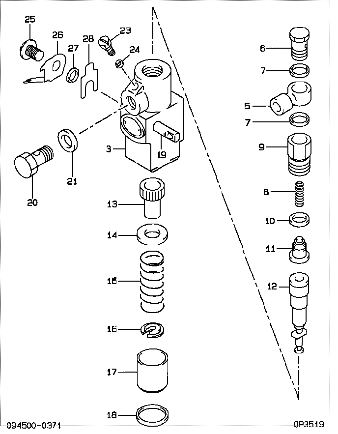
| 000. | [01] | 09450-00330 | PUMP ASSY, INJECTI | EZ01018 |
| 003. | [01] | 09011-00811 | HOUSING SUB-ASSY, | |
| 005. | [01] | 09005-90040 | NIPPLE, DELIVERY V | EZ00965005 |
| 006. | [01] | 09024-50071 | SCREW, HOLLOW | EZ00965XX006 |
| 007. | [02] | 09005-80040 | WASHER, NIPPLE | EZ00965XX007 |
| 008. | [01] | 09013-60010 | SPRING, DELIVERY V | 85265-00021 |
| 009. | [01] | 09013-10091 | HOLDER, DELIVERY V | EZ00965XX009 |
| 010. | [01] | 09013-70010 | GASKET, DELIVERY V | 85265-00019 |
| 011. | [01] | 09014-00010 | VALVE SUB-ASSY, IN | 09014-00010 |
| 012. | [01] | 09015-00961 | ELEMENT SUB-ASSY, | EZ01184 |
| 013. | [01] | 09016-10220 | SLEEVE, PLUNGER CO | EZ0066313 |
| 014. | [01] | 09016-30010 | SEAT, SPRING, UPR | 09016-30010 |
| 015. | [01] | 09016-40140 | SPRING, PUMP PLUNG | EZ0096515 |
| 016. | [01] | 09016-50010 | SEAT, SPRING, LWR | 85265-00031 |
| 017. | [01] | 09021-60011 | SLEEVE, GUIDE | EZ0096517 |
| 018. | [01] | 09018-70010 | RING, SNAP | EZ00663018 |
| 019. | [01] | 09021-20150 | RACK, CONTROL | EZ0066319 |
| 020. | [01] | 94918-00310 | SCREW, HOLLOW | 85265-00078 |
| 021. | [02] | 09022-20011 | WASHER, FUEL PIPE | 85265-00048 |
| 021. | [02] | 09022-20070 | WASHER, FUEL PIPE | 85265-00079 |
| 023. | [01] | 09024-40010 | SCREW, AIR BLEEDER | 09024-40010 |
| 024. | [01] | 09024-30010 | PACKING, AIR BLEED | 09024-30010 |
| 025. | [01] | 94904-10650 | BOLT, SLOTTED HEXA | EZ0066325 |
| 026. | [01] | 09026-10021 | POINTER | EZ0066326 |
| 027. | [1C] | 09026-20010 | WASHER, CONPENSATI | EZ0066327 |
| 027. | [1C] | 09026-30010 | WASHER, CONPENSATI | EZ0066327 |
| 027. | [1C] | 09026-40010 | WASHER, CONPENSATI | EZ0066327 |
| 027. | [1C] | 09026-50010 | WASHER, CONPENSATI | EZ0066327 |
Include in #3:
09450-00330
as PUMP ASSY, INJECTI
Cross reference number
| Part num | Firm num | Firm | Name |
| 09450-00330 | EZ01018 | PUMP ASSY, INJECTI | |
| EZ01018 | MITSUBISHI | PUMP ASSY, INJECTI |
Information:
Operation of ATAAC
Inlet air is pulled through the air cleaner, compressed and heated by the compressor wheel in the compressor side of the turbocharger to about 150°C (300°F). The heated air is then pushed through the air to air aftercooler core and moved to the air inlet manifold in the cylinder head at about 43°C (110°F).
Radiator Core (1) and Aftercooler Core (2).Cooling the inlet air increases combustion efficiency, which helps to lower fuel consumption and increase horsepower output. The aftercooler core (2) is a separate cooler core installed behind the standard radiator core (1). Ambient temperature is moved across both cores by the engine fan- this cools the turbocharged inlet air and the engine coolant.Lower inlet air temperature allows more air to enter the cylinder. More complete fuel combustion and reduced exhaust emissions are the results. Air-to-air aftercoolers can achieve charge air temperatures lower than water-to-air systems. The lower air temperatures provide improved efficiency.
To maintain an adequate water pump cavitation temperature for efficient water pump performance in an Air-to-Air Aftercooled engine: Caterpillar recommends that the coolant mix contain a minimum of 30 percent Caterpillar Antifreeze, or equivalent.
Air Inlet System
An air hose failure or a significant air inlet system leak will cause a large drop in boost pressure and power. The engine can be operated at this power level for a short period of time, however, sustained operation under this condition should be avoided.A slight reduction in power or response, or a small increase in exhaust temperature may indicate a small air leak in the charge air cooler core or piping.If air leaking is suspected, inspect the air inlet hoses, elbows and gaskets for cracks or damage. Replace the parts as needed. Check for loose clamps and tighten the clamps as needed.Radiator Restrictions
Caterpillar discourages the use of air flow restriction devices mounted in front of radiators with air-to-air aftercooled engines. Air flow restriction can cause higher exhaust temperatures, power loss, excessive fan usage, and a reduction in fuel economy.If an air flow restriction device must be used, the device should have a permanent opening directly in line with the fan hub. The device must have a minimum opening dimension of at least 770 cm2 (120 in2).A centered opening, directly in line with the fan hub, is specified to provide sensing when viscous fan drives are used and/or to prevent an interrupted air flow on the fan blades. Interrupted air flow on the fan blades could cause a fan failure.Caterpillar recommends that a package include an inlet manifold temperature device, such as a light indicator, buzzer, etc., set at 65°C (150°F) and/or installation of an inlet air temperature gauge. For the ATAAC (Air-To-Air Aftercooled) engines, air temperature in the inlet manifold should not exceed 65°C (150°F). Temperatures exceeding this limit can cause power loss and potential engine damage.This temperature provides engine protection for full restriction device closure. This temperature can also serve as a diagnostic tool for a malfunction of the charge air cooling system. It is not anticipated that