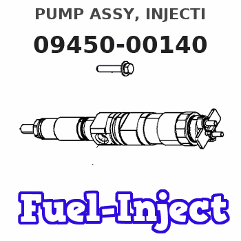
Information pump assy, injecti
Rating:
Components :
| 001. | PUMP ASSY, INJECTI | 09450-00140 |
Scheme ###:
| 000. | [01] | 09450-00140 | PUMP ASSY, INJECTI | 14381-51012 |
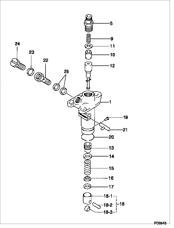
| 001. | [01] | 09011-00640 | HOUSING SUB-ASSY, | |
| 005. | [01] | 09013-10031 | HOLDER, DELIVERY V | 14109-51221 |
| 009. | [01] | 09013-60020 | SPRING, DELIVERY V | 14205-51230 |
| 010. | [01] | 09014-00030 | VALVE SUB-ASSY, IN | 15021-51031 |
| 011. | [01] | 09013-70020 | GASKET, DELIVERY V | 15021-51241 |
| 012. | [01] | 09015-00471 | ELEMENT SUB-ASSY, | 14123-51041 |
| 013. | [01] | 09016-10110 | SLEEVE, PLUNGER CO | 14109-51390 |
| 014. | [01] | 09016-30082 | SEAT, SPRING, UPR | 15221-51271 |
| 015. | [01] | 09016-40041 | SPRING, PUMP PLUNG | 14109-51280 |
| 016. | [01] | 09030-10060 | SEAT, SPRING, LWR | 15021-51291 |
| 017. | [1C] | 09031-10310 | PLATE, TAPPET ADJU | |
| 017. | [1C] | 09031-10300 | PLATE, TAPPET ADJU | |
| 017. | [1C] | 09031-10170 | PLATE, TAPPET ADJU | |
| 017. | [1C] | 09031-10160 | PLATE, TAPPET ADJU | |
| 017. | [1C] | 09031-10140 | PLATE, TAPPET ADJU | |
| 017. | [1C] | 09031-10130 | PLATE, TAPPET ADJU | 15221-51491 |
| 017. | [1C] | 09031-10120 | PLATE, TAPPET ADJU | |
| 017. | [1C] | 09031-10110 | PLATE, TAPPET ADJU | |
| 017. | [1C] | 09031-10010 | PLATE, TAPPET ADJU | 14109-51301 |
| 018. | [01] | 09017-00170 | TAPPET SUB-ASSY,IN | 15221-51071 |
| 018-001. | [01] | 09017-10022 | TAPPET, INJECTION | 15021-51990 |
| 018-002. | [01] | 09017-60020 | PIN, INJECTION PUM | 15021-51970 |
| 018-003. | [01] | 09217-60010 | ROLLER, FEED PUMP | 15109-52931 |
| 019. | [01] | 09018-30010 | PIN, INJECTION PUM | 14109-51250 |
| 020. | [01] | 09018-40060 | RING, CLAMP | |
| 021. | [01] | 09021-00160 | RACK ASSY, CONTROL | 14109-51261 |
| 022. | [01] | 09024-50080 | SCREW, HOLLOW | 15221-51321 |
| 023. | [01] | 94901-81020 | WASHER, COPPER PLA | 15221-96661 |
| 024. | [01] | 09024-40080 | SCREW, AIR BLEEDER | 15221-51351 |
| 025. | [02] | 09024-10010 | WASHER, AIR BLEEDE | 15221-96651 |
Include in #3:
09450-00140
as PUMP ASSY, INJECTI
Cross reference number
| Part num | Firm num | Firm | Name |
| 09450-00140 | 14381-5101 | PUMP ASSY, INJECTI | |
| 14381-51012 | KUBOTA | PUMP ASSY, INJECTI |
Information:
Clean and Inspect
Before working inside the generator, make sure that the starter motor can not be activated by any automatic or manual signal.When the engine-generator is operating, voltages up to 600V are present in these areas near or on the regulator:1. The regulator terminal strip2. The excitation transformer terminal strip (self-excited generator only).Do not short these terminals to ground with any part of the body or any conductive material. Loss of life or injury could result from electrical shock or injury from molten metal.An electrical shock can be received from the regulator capacitor (C1) when the engine-generator is not in operation. To avoid possible injury, discharge the stored charge using an 100 ohm resistor across C1 terminals.
Electronic components in the regulator can be damaged during generator operation if contact is made between the part and ground.
If Moisture is allowed to remain in contact with an electrical winding, some of the moisture will eventually be absorbed. This will lower the resistance of the winding insulation. The insulation used on the windings of Caterpillar generators is moisture resistant, but constant exposure to moisture will gradually lower the insulation's resistance.Dirt can make the problem worse because it can hold the moisture in contact with the insulation. Salt (from sea air) can also make the problem much worse. This is because salt tends to absorb moisture from the air. When the salt and moisture combine, they make a good electrical conductor.Clean the voltage regulator and generator of dirt and debris. Use a brush to loosen accumulations of dirt and a vacuum system for removal. Use of compressed air is not recommended, because of moisture present in the form of condensate.Carbon tracking on insulators can be caused by dirt or loose connections. These carbon paths must be cleaned or the insulators replaced. Failure to correct a carbon tracking problem will eventually result in a short in the electrical circuit.Visually check for loose or broken wires and connections. Check the wires and connections on the regulator assembly. Check that all circuit boards are fully plugged in their sockets. Check all wires and connections in the generator. Make any necessary repairs to the wiring as required. Refer to the "Electric Set Generator Service Manual" for testing and adjusting or disassembly and assembly procedures.Space Heaters
The SR4 generator can operate in high humidity conditions without problems. However, problems can occur when the generator is idle and the surrounding air is warmer than the generator. Moisture can form on the windings and result in poor performance and even result in damage to the windings. Whenever the generator is not in use, insure that the space heaters are in operation.An external source of either 115 or 230 (200 v at 50 Hz) volts A.C. is required to operate the space heaters. Space Heater Connection to External Source H1, H2, H3, H4. Terminal Strip Terminals If 115 VAC source is available, connect both heaters in parallel across the source (L1-L2). If 230 VAC source is available, connect both heaters in