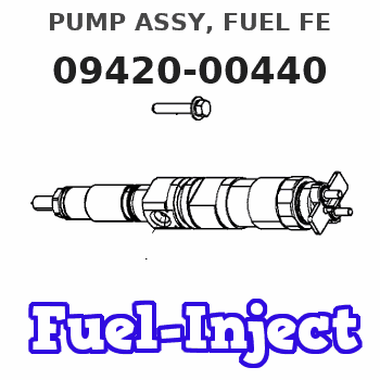
Information pump assy, fuel fe
Rating:
Compare Prices: .
As an associate, we earn commssions on qualifying purchases through the links below

IMIFAFTAbT Oil pump assembly ND094200-0440 094200-0440 Fits for HP0 Fuel Injection Pump ND0942000440 0942000440
IMIFAFTAbT Product Name: ND094200-0440 094200-0440 ND0942000440 0942000440 Oil pump assembly || Part number: ND094200-0440 094200-0440 ND0942000440 0942000440 || Fits for HP0 Fuel Injection Pump || 1 PCS Oil pump assembly || Note: Please confirm that the product shown in the part number is what you need. If you cannot confirm you can leave us a message and provide your engine serial number and nameplate
IMIFAFTAbT Product Name: ND094200-0440 094200-0440 ND0942000440 0942000440 Oil pump assembly || Part number: ND094200-0440 094200-0440 ND0942000440 0942000440 || Fits for HP0 Fuel Injection Pump || 1 PCS Oil pump assembly || Note: Please confirm that the product shown in the part number is what you need. If you cannot confirm you can leave us a message and provide your engine serial number and nameplate
Scheme ###:
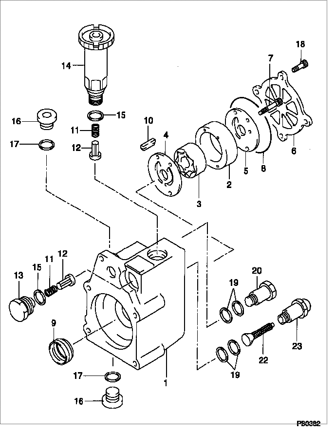
| 000. | [01] | 09420-00440 | PUMP ASSY, FUEL FE | |
| 001. | [01] | 09421-00090 | HOUSING SUB-ASSY, | |
| 002. | [01] | 09423-10060 | CASING, FEED PUMP | |
| 003. | [01] | 09423-00050 | PUMP SUB-ASSY, FUE | |
| 004. | [01] | 09424-10040 | PLATE, FEED PUMP S | |
| 005. | [01] | 09424-40040 | PLATE, FEED PUMP S | |
| 006. | [01] | 09425-10050 | COVER, FEED PUMP | |
| 007. | [04] | 09408-20040 | SCREW, SUPPLY PUMP | |
| 008. | [01] | 09408-60200 | O-RING, SUPPLY PUM | |
| 009. | [01] | 09408-70050 | SEAL, SUPPLY PUMP | |
| 010. | [01] | 09420-50060 | KEY | |
| 011. | [02] | 09212-40010 | SPRING, FEED PUMP | 5-15755002-0 |
| 012. | [02] | 09212-10011 | VALVE, FEED PUMP C | 5-15755001-0 |
| 013. | [01] | 09212-60010 | PLUG, FEED PUMP CH | |
| 014. | [01] | 09213-00360 | PUMP SUB-ASSY, PRI | |
| 015. | [02] | 09212-50010 | GASKET, CHECK VALV | 5-15759001-0 |
| 016. | [02] | 09031-70060 | PLUG, SCREW | |
| 017. | [02] | 94901-81500 | WASHER, COPPER PLA | |
| 018. | [04] | 94904-43320 | BOLT | |
| 019. | [04] | 94901-02490 | WASHER | 1-15619507-0 |
| 020. | [01] | 94918-00310 | SCREW, HOLLOW | 5-15759003-0 |
| 022. | [01] | 09222-00040 | FILTER, FEED PUMP | |
| 023. | [01] | 09222-30070 | SCREW, FUEL PIPE H | 5-15759002-0 |
Include in #3:
Cross reference number
| Part num | Firm num | Firm | Name |
| 09420-00440 | PUMP ASSY, FUEL FE |
Information:
1. Remove bolts (1) and the washers that hold rocker shaft assembly (2) in position.2. Remove rocker shaft assembly (2). Remove the O-ring seal from the rear rocker arm support bracket.3. Put identification marks on push rods (3) as to their location in the engine. Remove the push rods.Install Rocker Shaft Assembly & Push Rods
1. Install push rods (1). Make sure they are in their original location in the engine and in position in the valve lifters.
Loosen the adjusting screws on the rocker arms. This will prevent a bent valve or push rod during installation of the rocker shaft assembly.
2. Install a new O-ring seal in the rear rocker arm support bracket. Put 2P2506 Thread Lubricant on all of the bolts that hold the rocker shaft assembly in position except for the bolt that goes through the rear rocker arm support bracket.3. Put rocker shaft assembly (2) in position on the engine. Make sure the dowels in the support bracket are in alignment with the dowel holes in the cylinder head. Make sure the rocker arms are engaged with the push rods.4. Install the bolts and washers that hold the rocker shaft assembly in position. Tighten them until they are finger tight.
3304 Engine Sequence
3306 Engine Sequence5. Tighten the bolts that hold the rocker shaft as follows:a. Tighten the bolts in number sequence to a torque of 156 N m (115 lb ft).b. Tighten the bolts in number sequence to a torque of 250 17 N m (185 13 lb ft).c. Tighten the bolts again in number sequence to a torque of 250 17 N m (185 13 lb ft).6. See "Valve Clearance Setting" in Testing & Adjusting. Make an adjustment to the valves so the intake valves have 0.38 mm (.015 in) clearance and the exhaust valves have 0.64 mm (.025 in) clearance. Tighten the locknuts for the adjusting screws to a torque of 29 7 N m (21 5 lb ft).End By:a. install valve cover