Information pump assy, fuel fe
Rating:
Scheme ###:

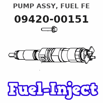
| 000. | [01] | 09420-00151 | PUMP ASSY, FUEL FE | |
| 001. | [01] | 09421-00090 | HOUSING SUB-ASSY, | |
| 002. | [01] | 09423-10050 | CASING, FEED PUMP | |
| 003. | [01] | 09423-00040 | PUMP SUB-ASSY, FUE | |
| 004. | [01] | 09424-10040 | PLATE, FEED PUMP S | |
| 005. | [01] | 09424-40040 | PLATE, FEED PUMP S | |
| 006. | [01] | 09425-10050 | COVER, FEED PUMP | |
| 007. | [04] | 09408-20040 | SCREW, SUPPLY PUMP | |
| 008. | [01] | 09408-60200 | O-RING, SUPPLY PUM | |
| 009. | [01] | 09408-70050 | SEAL, SUPPLY PUMP | |
| 010. | [01] | 09420-50030 | KEY | |
| 010. | [01] | 09420-50060 | KEY | |
| 011. | [02] | 09212-40010 | SPRING, FEED PUMP | S2256-21020-A |
| 012. | [02] | 09212-10011 | VALVE, FEED PUMP C | S2256-31041-A |
| 013. | [01] | 09212-60010 | PLUG, FEED PUMP CH | S2284-51350-A |
| 014. | [01] | 09213-00360 | PUMP SUB-ASSY, PRI | S2250-91370-A |
| 015. | [02] | 09212-50010 | GASKET, CHECK VALV | S2284-71680-A |
| 016. | [02] | 09031-70060 | PLUG, SCREW | S2284-51060-A |
| 017. | [02] | 94901-81500 | WASHER, COPPER PLA | S2284-71120-A |
| 018. | [04] | 94904-43320 | BOLT | S2281-52070-A |
| 019. | [04] | 94901-02490 | WASHER | S2287-71100-A |
| 020. | [01] | 94918-00310 | SCREW, HOLLOW | S2283-51310-A |
| 022. | [01] | 09222-00040 | FILTER, FEED PUMP | S2257-41040-A |
| 023. | [01] | 09222-30070 | SCREW, FUEL PIPE H | S2283-51370-A |
Include in #3:
09400-00235
as PUMP ASSY, FUEL FE
09420-00151
Cross reference number
| Part num | Firm num | Firm | Name |
| 09420-00151 | PUMP ASSY, FUEL FE |
Information:
D11N (74Z) Track-Type TractorIntroduction
This Special Instruction outlines the procedure for the installation of a 3508 Engine with electronic unit injection (EUI) into a D11N Tractor (74Z). The original engine in this machine was a 3508 Engine with mechanical unit injection (MUI). This Special Instruction does not cover conversion of the basic engine from MUI to EUI.The information covers a typical 3508 EUI Engine installation. It does not cover all situations one is likely to encounter, as a number of changes have been made to the machine since its introduction. Modifications and changes made by users and special attachments may also affect engine installation.During this engine installation a number of changes will be made to the tractor electrical system. Console mounted indicator lamps will be added to alert the operator to the need for air-cleaner servicing. Another lamp will signal that diagnostic information is present in the electronic control module (ECM) located on the engine. An engine overspeed indicator lamp will also be added to the console. The engine overspeed indicator is operated as part of the ECM. No changes will be made to the electronic monitoring system (EMS) which is part of the instrument panel. The dual cylinder ether starting aid system will be replaced by a single cylinder system.If a new or remanufactured EUI engine is being installed, the alternator will be located at the rear of the engine. The location of the refrigerant compressor, for the optional air conditioning system, has not been changed.Use care when installing the new components. Take note of the installation locations specified. Use care when making electrical connections between the new and existing components and systems.Reference Literature Parts Needed
Engine Removal
Disconnect the cables to the batteries to prevent the possibility of personal injury and/or damage to electrical or electronic equipment. Refer to Service Manual