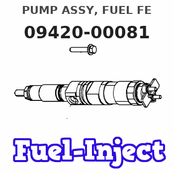
Information pump assy, fuel fe
Rating:
Compare Prices: .
As an associate, we earn commssions on qualifying purchases through the links below

IMIFAFTAbT Oil pump assembly ND094200-0081 094200-0081 Fits for HP0 Fuel Injection Pump ND0942000081 0942000081
IMIFAFTAbT Product Name: ND094200-0081 094200-0081 ND0942000081 0942000081 Oil pump assembly || Part number: ND094200-0081 094200-0081 ND0942000081 0942000081 || Fits for HP0 Fuel Injection Pump || 1 PCS Oil pump assembly || Note: Please confirm that the product shown in the part number is what you need. If you cannot confirm you can leave us a message and provide your engine serial number and nameplate
IMIFAFTAbT Product Name: ND094200-0081 094200-0081 ND0942000081 0942000081 Oil pump assembly || Part number: ND094200-0081 094200-0081 ND0942000081 0942000081 || Fits for HP0 Fuel Injection Pump || 1 PCS Oil pump assembly || Note: Please confirm that the product shown in the part number is what you need. If you cannot confirm you can leave us a message and provide your engine serial number and nameplate
Scheme ###:

| 000. | [01] | 09420-00081 | PUMP ASSY, FUEL FE | |
| 001. | [01] | 09421-00070 | HOUSING SUB-ASSY, | |
| 002. | [01] | 09423-10050 | CASING, FEED PUMP | |
| 002. | [01] | 09423-10060 | CASING, FEED PUMP | |
| 003. | [01] | 09423-00040 | PUMP SUB-ASSY, FUE | |
| 003. | [01] | 09423-00050 | PUMP SUB-ASSY, FUE | |
| 004. | [01] | 09424-10040 | PLATE, FEED PUMP S | |
| 005. | [01] | 09424-40040 | PLATE, FEED PUMP S | |
| 006. | [01] | 09425-10050 | COVER, FEED PUMP | |
| 007. | [04] | 09408-20040 | SCREW, SUPPLY PUMP | |
| 008. | [01] | 09408-60200 | O-RING, SUPPLY PUM | |
| 009. | [01] | 09408-70050 | SEAL, SUPPLY PUMP | |
| 010. | [01] | 09420-50060 | KEY | |
| 010. | [01] | 09420-50030 | KEY | |
| 011. | [02] | 09212-40010 | SPRING, FEED PUMP | |
| 012. | [02] | 09212-10011 | VALVE, FEED PUMP C | |
| 013. | [01] | 09212-60010 | PLUG, FEED PUMP CH | |
| 014. | [01] | 09213-00360 | PUMP SUB-ASSY, PRI | |
| 015. | [02] | 09212-50010 | GASKET, CHECK VALV | |
| 016. | [02] | 09031-70060 | PLUG, SCREW | |
| 017. | [02] | 94901-81500 | WASHER, COPPER PLA | |
| 018. | [04] | 94904-43320 | BOLT | |
| 019. | [04] | 09022-20070 | WASHER, FUEL PIPE | 16635Z6002 |
| 020. | [01] | 94918-00310 | SCREW, HOLLOW | 16753Z6002 |
| 022. | [01] | 09222-00040 | FILTER, FEED PUMP | |
| 023. | [01] | 09222-30070 | SCREW, FUEL PIPE H |
Include in #3:
09400-00133
as PUMP ASSY, FUEL FE
09420-00081
Cross reference number
| Part num | Firm num | Firm | Name |
| 09420-00081 | PUMP ASSY, FUEL FE |
Information:
Remove Valve Guide Seals
Start By:a. remove rocker shaft and push rods Valve guide seals for the inlet valves and O-ring seals for the exhaust valves can be removed without removal of the cylinder head by use of the method shown. Pressure air is used to hold the valves in position while the valve springs and retainers are removed. Use an old fuel injection nozzle to make an air chuck adapter. 1. Remove the fuel injection nozzle assembly, and put the piston on TDC (top dead center) for the respective cylinder for which the valve stem seal and O-ring seals are to be removed.2. Install air chuck adapter (2). Fasten a pressure air source to pressurize the cylinder.3. Use tooling (A) to compress the valve springs. Use magnet bar (1) to hold the keepers.4. Remove tool (A), and remove the valve springs and retainer. 5. Remove exhaust valve O-ring seal (3) and inlet valve guide seal (4).
Do not release air pressure in the cylinder until the valve springs and retainer have been installed. Failure to do so will let the valve fall into the top of the piston. If the piston is not at TDC (top dead center) the valve can fall into the cylinder making cylinder head removal necessary.
Install Valve Guide Seals
1. Install spring seating washer (1). 2. Put clean engine oil on the part of valve guide seal (2) that makes contact with the valve stem. Install valve guide seal (2).
The closed coil of the spring must be toward the cylinder rod.
3. Put inner and outer springs (4) and retainer (3) in position.
The locks can be thrown from the valve when the compressor is released if they are not in their correct position on the valve stem.
4. Use tool (A) to compress the valve springs so the keepers can be installed.5. Use tool (B) to install the keepers.6. Repeat Steps 1-4 for O-ring seals (5) on the exhaust valve.7. Move the piston off T.D.C. (top dead center) and tap the valve spring retainer with a soft hammer to be sure the retainers are properly seated.8. Install the fuel injection nozzle assembly.End By:a. install rocker shaft and push rods