Information body assy, supply
Rating:
Scheme ###:

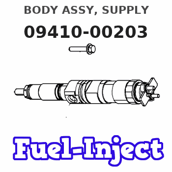
| 000. | [01] | 09410-00203 | BODY ASSY, SUPPLY | |
| 001. | [01] | 09411-00150 | HOUSING SUB-ASSY, | |
| 002. | [02] | 09413-10020 | HOLDER, DELIVERY V | |
| 003. | [02] | 09413-30020 | STOPPER, DELIVERY | |
| 004. | [02] | 09408-60090 | O-RING, SUPPLY PUM | |
| 005. | [02] | 09013-61252 | SPRING, DELIVERY V | |
| 006. | [02] | 09413-70010 | GASKET, DELIVERY V | |
| 007. | [02] | 09414-00021 | VALVE SUB-ASSY, SU | |
| 008. | [02] | 09415-00132 | ELEMENT SUB-ASSY, | |
| 008. | [02] | 09415-00240 | ELEMENT SUB-ASSY, | |
| 009. | [06] | 09408-60100 | O-RING, SUPPLY PUM | |
| 010. | [04] | 94901-35880 | WASHER, PLATE, SK | 22885-2290A |
| 011. | [04] | 92156-08081 | NUT, FLANGE | |
| 012. | [02] | 09416-20031 | SEAT, SPRING, UPR | |
| 013. | [02] | 09416-40022 | SPRING, PUMP PLUNG | |
| 014. | [02] | 09416-50031 | SEAT, SPRING, LWR | |
| 015. | [02] | 09417-00040 | TAPPET SUB-ASSY, S | |
| 015. | [02] | 09417-00090 | TAPPET SUB-ASSY, S | |
| 015. | [02] | 09417-00110 | TAPPET SUB-ASSY, S | |
| 016. | [01] | 09419-10361 | CAMSHAFT, SUPPLY P | |
| 017. | [02] | 94910-10220 | BEARING, ROLLER | |
| 018. | [01] | 09410-40130 | COVER, BEARING | |
| 019. | [01] | 94915-03150 | SEAL, OIL | |
| 020. | [01] | 09408-60150 | O-RING, SUPPLY PUM | |
| 021. | [2C] | 09409-50170 | PLATE, BEARING COV | |
| 021. | [2C] | 09409-50180 | PLATE, BEARING COV | |
| 021. | [2C] | 09409-50190 | PLATE, BEARING COV | |
| 021. | [2C] | 09409-50200 | PLATE, BEARING COV | |
| 021. | [2C] | 09409-50210 | PLATE, BEARING COV | |
| 023. | [04] | 94904-77010 | BOLT, W/WASHER | |
| 024. | [01] | 09408-60160 | O-RING, SUPPLY PUM | |
| 025. | [01] | 09408-60170 | O-RING, SUPPLY PUM | |
| 026. | [1C] | 09409-30090 | WASHER, SUPPLY PUM | |
| 026. | [1C] | 09409-30100 | WASHER, SUPPLY PUM | |
| 026. | [1C] | 09409-30110 | WASHER, SUPPLY PUM | |
| 026. | [1C] | 09409-30120 | WASHER, SUPPLY PUM | |
| 027. | [02] | 09404-00021 | OVERHAUL KIT, SUPP | |
| 028. | [01] | 02960-00580 | SENSOR ASSY, CRANK | 89411-1290 |
| 028-001. | [01] | 94914-06310 | O-RING | |
| 029. | [2C] | 09409-60050 | PLATE, SENSOR SHIM | |
| 029. | [2C] | 09409-60060 | PLATE, SENSOR SHIM | |
| 029. | [2C] | 09409-60070 | PLATE, SENSOR SHIM | |
| 029. | [2C] | 09409-60080 | PLATE, SENSOR SHIM | |
| 030. | [02] | 90200-06081 | WASHER, PLATE | |
| 031. | [02] | 90107-06161 | BOLT, HEXAGON | |
| 032. | [01] | 09031-00500 | VALVE ASSY, OVERFL | S2210-71760-A |
| 033. | [05] | 94901-02490 | WASHER | S2287-71100-A |
| 035. | [01] | 94918-00310 | SCREW, HOLLOW | S2283-51310-A |
| 036. | [02] | 94901-02470 | WASHER | S2284-71900-A |
| 038. | [01] | 09024-50120 | SCREW, HOLLOW | 22835-1060A |
| 040. | [01] | 94901-81500 | WASHER, COPPER PLA | S2284-71120-A |
| 041. | [01] | 09031-70060 | PLUG, SCREW | S2284-51060-A |
| 042. | [02] | 94901-02500 | WASHER | S2284-71920-A |
| 044. | [01] | 94918-00420 | SCREW, HOLLOW | S2283-51180-A |
| 045. | [4C] | 90218-06140 | WASHER, PLATE | 22867-1650A |
| 045. | [4C] | 90218-06130 | WASHER, PLATE | |
| 045. | [4C] | 90218-06120 | WASHER, PLATE | |
| 046. | [01] | 09020-70120 | RING, WEAR | |
| 047. | [01] | 09020-70100 | RING, WEAR | |
| 048. | [02] | 09533-10011 | STOPPER, W/GASKET | |
| 048. | [02] | 09533-10020 | STOPPER, W/GASKET |
Include in #3:
Cross reference number
| Part num | Firm num | Firm | Name |
| 09410-00203 | BODY ASSY, SUPPLY |
Information:
Introduction
Maintaining the accuracy of fuel system test equipment (fuel pump test stands and nozzle/injector pop testers) should be a high priority in each fuel system service shop to assure high quality repairs and satisfied customers.This procedure provides information on how to select, test and chart reference parts (using available fuel system parts in a dealer's shop) for checking and maintaining accuracy of fuel systems test equipment.Creating reference parts is recommended in addition to preventative maintenance recommendations discussed in Caterpillar Special Instructions.Creating a reference part will allow each fuel system technician to check their test stand or pop tester as a complete unit.Reference parts should be selected from used fuel system components that are available and in good working order. Selected reference parts must be identified so it will not mistakenly be installed in an engine.Fuel Pump Reference Parts
1. Select a pump typically serviced in your dealer shop. Do NOT use electronic (PEEC) fuel pumps as reference parts. A 3306B pump is recommended for your reference pump.2. If necessary, disassemble and visually inspect pump cam, lifters, plunger and barrel, etc. to assure all internal components are in good condition.3. Check pump plunger and barrel bonnet nut torque. Torque nuts to recommended value according to the service manual.4. Back out the pump governor load stop(s) and idle setting screws.5. Obtain the required pump rack zero pin. It is recommended each reference pump have its own zero pin (order a spare from the parts department) and permanently attach to the reference pump.6. Install the reference pump on the test stand.7. Make sure the test stand has the latest master fuel nozzles. All master nozzles must have the same part number.8. Inspect each test stand high pressure fuel line inside diameter (ID) for "close-in" from repeated use.Repeated assembly of the high pressure fuel lines can cause the tubing's inside diameter to collapse or "close-in", resulting in low delivery volume. Testing fuel injection pumps using worn or partially closed high pressure fuel lines will cause inaccurate test results. All high pressure fuel lines used on the test stand should be checked every three months.
Always use a wrench to hold the hex fitting on top of the master nozzle, when assembling or disassembling lines. If a wrench is not used, the master nozzle and manifold it is installed into may be damaged.
Check fuel line for "Close-in" Do NOT use fuel lines with an ID (inside diameter) LESS than 1.191 mm (0.0469 in). The fuel line ID can be checked using a 1.2 mm (.047 in) drill.If the drill bit can NOT be inserted into the fuel line high pressure hole, either drill out the line using a 1.6 mm (.063 in) drill or replace the fuel line with a new line. Use the same length and internal diameter lines each time the reference pump is tested.
If the fuel lines are not completely and thoroughly cleaned out after the drilling procedure, metal particles or foreign debris in the line will damage the master nozzles and