Information body assy, supply
Rating:
Scheme ###:
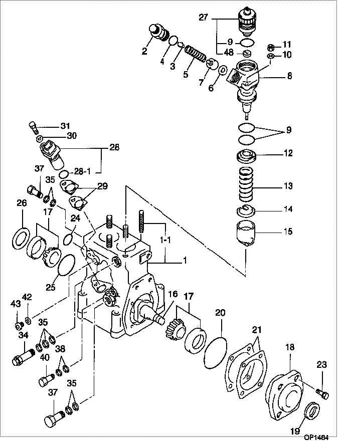
| 000. | [01] | 09410-00021 | BODY ASSY, SUPPLY | |
| 001. | [01] | 09411-00021 | HOUSING SUB-ASSY, | |
| 001-001. | [04] | 94904-32160 | BOLT, STUD | |
| 002. | [02] | 09413-10020 | HOLDER, DELIVERY V | |
| 003. | [02] | 09413-30020 | STOPPER, DELIVERY | |
| 004. | [02] | 09408-60090 | O-RING, SUPPLY PUM | |
| 005. | [02] | 09013-60770 | SPRING, DELIVERY V | |
| 006. | [02] | 09413-70010 | GASKET, DELIVERY V | |
| 007. | [02] | 09414-00021 | VALVE SUB-ASSY, SU | |
| 008. | [02] | 09415-00021 | ELEMENT SUB-ASSY, | |
| 008. | [02] | 09404-00230 | OVERHAUL KIT, SUPP | |
| 009. | [06] | 09408-60100 | O-RING, SUPPLY PUM | |
| 010. | [04] | 94901-35880 | WASHER, PLATE, SK | 22885-2290A |
| 011. | [04] | 90196-08651 | NUT, HEXAGON | 22825-1380A |
| 012. | [02] | 09416-20020 | SEAT, SPRING, UPR | |
| 013. | [02] | 09416-40010 | SPRING, PUMP PLUNG | |
| 014. | [02] | 09416-50021 | SEAT, SPRING, LWR | |
| 015. | [02] | 09417-00020 | TAPPET SUB-ASSY, S | |
| 015. | [02] | 09417-00030 | TAPPET SUB-ASSY, S | |
| 015. | [02] | 09417-00080 | TAPPET SUB-ASSY, S | |
| 016. | [01] | 09419-10022 | CAMSHAFT, SUPPLY P | |
| 017. | [02] | 94910-10210 | BEARING, ROLLER | |
| 018. | [01] | 09410-40020 | COVER, BEARING | |
| 019. | [01] | 94915-02820 | SEAL, OIL | S2282-71750-A |
| 020. | [01] | 09408-60120 | O-RING, SUPPLY PUM | |
| 021. | [2C] | 09409-50160 | PLATE, BEARING COV | |
| 021. | [2C] | 09409-50150 | PLATE, BEARING COV | |
| 021. | [2C] | 09409-50140 | PLATE, BEARING COV | |
| 021. | [2C] | 09409-50130 | PLATE, BEARING COV | |
| 021. | [2C] | 09409-50100 | PLATE, BEARING COV | |
| 023. | [04] | 94904-77040 | BOLT, W/WASHER | |
| 024. | [01] | 09408-60110 | O-RING, SUPPLY PUM | |
| 025. | [01] | 09408-60130 | O-RING, SUPPLY PUM | |
| 026. | [1C] | 09409-30080 | WASHER, SUPPLY PUM | |
| 026. | [1C] | 09409-30070 | WASHER, SUPPLY PUM | |
| 026. | [1C] | 09409-30060 | WASHER, SUPPLY PUM | |
| 026. | [1C] | 09409-30050 | WASHER, SUPPLY PUM | |
| 027. | [02] | 09404-00100 | OVERHAUL KIT, SUPP | |
| 028. | [01] | 02960-00580 | SENSOR ASSY, CRANK | 89411-1290A1 |
| 028-001. | [01] | 94914-06310 | O-RING | |
| 029. | [2C] | 09409-60080 | PLATE, SENSOR SHIM | |
| 029. | [2C] | 09409-60070 | PLATE, SENSOR SHIM | |
| 029. | [2C] | 09409-60060 | PLATE, SENSOR SHIM | |
| 029. | [2C] | 09409-60050 | PLATE, SENSOR SHIM | |
| 030. | [01] | 90200-06081 | WASHER, PLATE | SZ201-06001 |
| 031. | [01] | 90100-06161 | BOLT, HEXAGON | 1 010 0616 05 |
| 034. | [01] | 09031-00460 | VALVE ASSY, OVERFL | 22107-1750A |
| 035. | [07] | 94901-02490 | WASHER | S2287-71100-A |
| 037. | [02] | 94918-00310 | SCREW, HOLLOW | S2283-51310-A |
| 038. | [02] | 94901-02470 | WASHER | S2284-71900-A |
| 040. | [01] | 94918-00060 | SCREW, HOLLOW | S2283-51110-A |
| 041. | [02] | 09001-40022 | CAP, VALVE HOLDER | 22104-1330 |
| 042. | [01] | 94901-81500 | WASHER, COPPER PLA | S2284-71120-A |
| 043. | [01] | 09031-70060 | PLUG, SCREW | S2284-51060-A |
| 048. | [01] | 09533-10020 | STOPPER, W/GASKET |
Include in #3:
09400-00041
as BODY ASSY, SUPPLY
09410-00021
Cross reference number
| Part num | Firm num | Firm | Name |
| 09410-00021 | BODY ASSY, SUPPLY |
Information:
D11N 74Z1-729Introduction
The Automatic Ether Injection System controls the amount of ether to be injected into the engine intake manifold during cold weather starting. Correct operation of this electronically controlled system is required to prevent possible damage to the engine during cold-start conditions.This instruction gives the procedure needed to install the automatic ether injection system for the engine in a D11N Tractor, within the product identification number range given. Installation of this ether injection system will ensure that the correct amount of ether is injected when ether is required during the starting procedure.Do not perform any procedure, outlined in this publication, or order any parts until you read and understand the information contained within. Before starting the installation procedure, make certain the machine disconnect switch is in the OFF position.Reference: Service Manual, form SENR4705. Necessary Parts
Installation Procedure for Components of Automatic Ether Injection System
If the machine is equipped with an earlier version ether starting aid group, remove the entire system with the exception of the in-cab, dash mounted, 8C9812 Switch and the tubing to the turbocharger outlet adapters. This consists of two nozzles, two tubes from the nozzles to a tee, and the tee.All electrical wiring from the earlier system must also be removed, including the wiring to the 8C9812 Switch.Installation of Components in the Cover Assembly
The cover assembly provides a mounting location and protection for the solenoid valve, ether cylinders, reset switch (and the reset switch bracket), and the electronic control unit (ECU). This complete unit will be mounted toward the rear of the fender, on the left side of the machine. The location will be to the rear of the air conditioner/heater, but forward of the fuel tank.All existing components currently located in this area must be removed and relocated. A section of the skid plate, (the section from the rear edge of the air conditioner/heater to the fuel tank) must be removed. 1. Put four 8C5607 Mounts into the holes provided in each of the two 8E1355 Plates (2). Insert an 8C5608 Spacer into each shock mount. Use 5P2675 Bolts (1) with 9X6165 Washers to fasten the two 8E1355 Plates (2) to plates (3) in the cover assembly.Use a crimping tool to install a 2L8079 Terminal on one end of the 5P5624 Wire, then install a 2L8077 Terminal on the other end.Use one of the bolts to fasten this newly fabricated wire assembly (4) into position [between the upper bolt and washer for one of the plates (2)] as shown.
The ECU and the bolts (5) that retain it are shown here for location purposes only. Installation of the ECU is not to be done until all welding procedures are completed.
2. Install a 5P0598 Clamp through slot (A) of each ether valve assembly mounting plate (6). Remove plug (B) at the bottom of each solenoid valve. 3. Install a 7X1063 Orifice Fitting (7) (left hand thread) in the hole at each location where a plug (B) was removed. Make sure that filter (8) is installed and