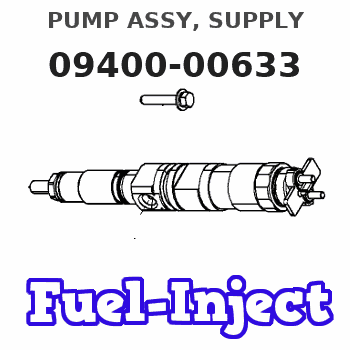
Information pump assy, supply
Rating:
Compare Prices: .
As an associate, we earn commssions on qualifying purchases through the links below

HP0 Fuel Injection Pump for Komatsu SAA12V140E-3 Engine PC2000-8 WA800-3 D475A-5 HD785-7 Excavator Loader Truck 094000-0633 6219-71-1201
KoovDem Part Number: 094000-0633, 6219-71-1201. || Compatible Model: For Komatsu SAA12V140E-3 Engine PC2000-8 WA800-3 D475A-5 HD785-7 Excavator Loader Truck. || Effective and Reliable: Utilizing cutting-edge technology, this system delivers effective and reliable fuel supply, guaranteeing smooth vehicle performance. || Rugged and Dependable: With a track record of being rigorously tested and proven, this product offers durability and reliability, ensuring it operates consistently even in the harshest of environments. || Straightforward Installation: With a user-friendly interface, installing this product is a breeze. Simply plug it in and you're good to go, no technical expertise needed.
KoovDem Part Number: 094000-0633, 6219-71-1201. || Compatible Model: For Komatsu SAA12V140E-3 Engine PC2000-8 WA800-3 D475A-5 HD785-7 Excavator Loader Truck. || Effective and Reliable: Utilizing cutting-edge technology, this system delivers effective and reliable fuel supply, guaranteeing smooth vehicle performance. || Rugged and Dependable: With a track record of being rigorously tested and proven, this product offers durability and reliability, ensuring it operates consistently even in the harshest of environments. || Straightforward Installation: With a user-friendly interface, installing this product is a breeze. Simply plug it in and you're good to go, no technical expertise needed.

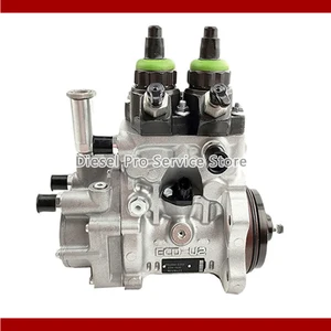
6219-71-1201 Fuel Injection Pump Fits For Komatsu Engine SAA12V140E-3 Loader WA800-3 Excavator PC2000-8 Truck D475A-5 HD785 094000-0633
KoovDem Part Number: 6219-71-1201 094000-0633 6219711201 Note: Please check the fitment carefully before purchase. Or just tell us the part number you need. || Part Name: Fuel Injection Pump || The SAA12V140E-3 is a robust diesel engine with a displacement of 38.8 liters and electronic fuel injection for fuel efficiency. With 930 horsepower, it excels in heavy-duty tasks. Its advanced design ensures smooth operation, making it ideal for industrial and commercial vehicles like construction equipment, mining machinery, and power generation systems. || Compatible with the Komatsu Engine SAA12V140E-3 and suitable for various heavy-duty machinery such as the WA800-3 loader, PC2000-8 excavator, D475A-5 truck, and HD785 haul truck. Specifically designed to meet the needs of these powerful vehicles, ensuring optimal performance and reliability. Trust in its quality and precision engineering for replacement or upgrade parts for your Komatsu equipment, keeping your machinery running smoothly for years to come. || Included in the package is one piece of the Fuel Injection Pump with the part number 6219-71-1201 and the reference number 094000-0633.
KoovDem Part Number: 6219-71-1201 094000-0633 6219711201 Note: Please check the fitment carefully before purchase. Or just tell us the part number you need. || Part Name: Fuel Injection Pump || The SAA12V140E-3 is a robust diesel engine with a displacement of 38.8 liters and electronic fuel injection for fuel efficiency. With 930 horsepower, it excels in heavy-duty tasks. Its advanced design ensures smooth operation, making it ideal for industrial and commercial vehicles like construction equipment, mining machinery, and power generation systems. || Compatible with the Komatsu Engine SAA12V140E-3 and suitable for various heavy-duty machinery such as the WA800-3 loader, PC2000-8 excavator, D475A-5 truck, and HD785 haul truck. Specifically designed to meet the needs of these powerful vehicles, ensuring optimal performance and reliability. Trust in its quality and precision engineering for replacement or upgrade parts for your Komatsu equipment, keeping your machinery running smoothly for years to come. || Included in the package is one piece of the Fuel Injection Pump with the part number 6219-71-1201 and the reference number 094000-0633.

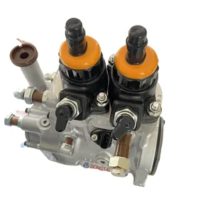
Fuel Injection Pump 094000-0633 6219-71-1201 For Komatsu Engine SAA12V140E-3
oiasdfhjdg Product name:Fuel Injection Pump || Part Number:094000-0633 6219-71-1201 || APPlication:For Komatsu Engine SAA12V140E-3 || 1.Please carefully compare the OE numbers before purchasing the product to match your original parts and avoid wasting your valuable time. || 2.Please ensure to provide us with the correct, accurate, and detailed delivery address and contact information
oiasdfhjdg Product name:Fuel Injection Pump || Part Number:094000-0633 6219-71-1201 || APPlication:For Komatsu Engine SAA12V140E-3 || 1.Please carefully compare the OE numbers before purchasing the product to match your original parts and avoid wasting your valuable time. || 2.Please ensure to provide us with the correct, accurate, and detailed delivery address and contact information
You can express buy:
USD 669.12
17-05-2025
17-05-2025
Diesel Fuel Injection Pump 094000-0633 6219-71-1201 6219711201 For SA12VD140 6219-71-1201

USD 778
13-05-2025
13-05-2025
Diesel Fuel Injection Pump 094000-0633 6219-71-1201 6219711201 For SA12VD140 6219-71-1201
USD 1308.36
19-05-2025
19-05-2025
HP0 Pump 094000-0633 6219-71-1201 For Komatsu PC2000-8
Images:
USD 456.46

[19-May-2025]
USD 665.76

[11-May-2025]
USD 2085.26

[19-May-2025]
USD 740.27

[19-May-2025]
Include in #3:
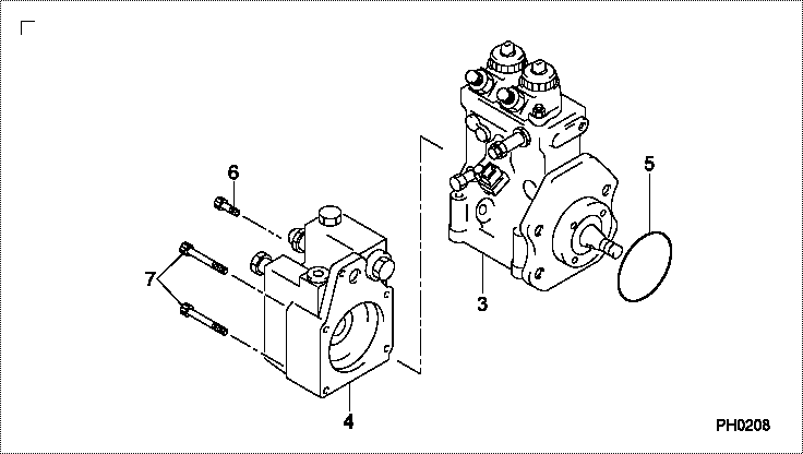
Cross reference number
| Part num | Firm num | Firm | Name |
| 09400-00633 | 62197-1112 | PUMP ASSY, SUPPLY |
Information:
Remove Cylinder Head Assembly
Start By:a. remove rocker shaft and push rodsb. remove inlet and exhaust manifoldc. remove fuel injection linesd. remove fuel injection nozzle assemblies 1. Drain the cooling system.2. Remove bolt (2) and spacer (1). 3. Remove clip (3) that holds line (4) to the cylinder head. 4. Remove bolts (5) that hold fuel filter base and filter (6) to the cylinder head. 5. Fasten a chain and hoist to the cylinder head lifting brackets. Remove the bolts and nuts that hold the cylinder head. Remove the cylinder head. Weight of the cylinder head is 41 kg (90 lb.). 6. Remove cylinder head gasket (7).7. Check the condition of the cylinder head assembly before installation.Install Cylinder Head Assembly
1. Use a tap of the correct size to clean each threaded hole in the cylinder block for the cylinder head mounting bolts.2. Thoroughly clean the surface for the cylinder head gasket on the cylinder head assembly and cylinder block.
Be sure the gasket is positioned so that all coolant passages in the cylinder block can be seen through the gasket.
3. Put cylinder head gasket (1) in place on the studs in the cylinder block. 4. Put the cylinder head in position on the studs.5. Put clean engine oil on the bolt threads, and install the bolts that hold the cylinder head. 6. Tighten the bolts and nuts in the number sequence shown as follows:a. Tighten all bolts and nuts in number sequence to a torque of 45 N m (35 lb.ft.).b. Tighten all bolts and nuts in number sequence to a torque of 95 N m (70 lb.ft.).c. Again, tighten all bolts and nuts in number sequence to a final torque of 135 N m (100 lb.ft.). Retighten the cylinder head bolts and nuts after the engine has run under part load for approximately thirty minutes.a. If the bolts and nuts move before the correct final torque is reached, retighten every thing in the sequence again to the final torque of 135 N m (100 lb.ft.).b. If the bolts and nuts do not move before the correct final torque is reached, back each one off 30 to 60°, and retighten again, in the sequence shown, to the final torque. After all the bolts and nuts are retightened, check the first 10 positions to make sure they are tightened to the correct torque. 7. Install fuel filter base and filter (2) on the cylinder head with bolts (3).8. Install clip (4) that holds fuel line (5) to the cylinder head.9. Install the alternator bracket bolt and spacer in the cylinder head.End By:a. install fuel injection nozzle assembliesb. install fuel injection linesc. install inlet and exhaust manifoldd. install rocker shaft and push rods