Information pump assy, supply

Rating:
KIT List:
| Pump assy, supply | 0940400030 |
Compare Prices: .
As an associate, we earn commssions on qualifying purchases through the links below

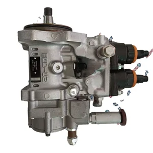
094000-0380 6156-71-1111 6D125 Engine Injection Pump Suitable for Komatsu PC400-7 PC450-7
OfkZynodor Part Name: Injection Pump || Part Number: 6156-71-1111 094000-0380 || Application: Suitable for Komatsu PC400-7 PC450-7 || Please make sure to carefully compare the photos and check the part numbers before making the purchase. If you are unable to confirm your engine model or part number, please leave us a message and we will assist you in confirming that the product you purchase is the one you need. || Your order is not merely a single purchase but the beginning of a cooperative journey, aiming to ensure the safe and smooth operation of your vehicle. We are proud to offer you reliable precision engineering components and unparalleled services.
OfkZynodor Part Name: Injection Pump || Part Number: 6156-71-1111 094000-0380 || Application: Suitable for Komatsu PC400-7 PC450-7 || Please make sure to carefully compare the photos and check the part numbers before making the purchase. If you are unable to confirm your engine model or part number, please leave us a message and we will assist you in confirming that the product you purchase is the one you need. || Your order is not merely a single purchase but the beginning of a cooperative journey, aiming to ensure the safe and smooth operation of your vehicle. We are proud to offer you reliable precision engineering components and unparalleled services.

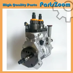
CR HP0 Fuel Injection Pump for Komatsu 6D125 SAA6D125E-3 SAA6D125E-3A Engine PC400-7 PC450-7 PC460-7 Excavator 6156-71-1111 6156-71-1112 094000-0380
KoovDem Part Number: 094000-0380 6156-71-1111 6156-71-1112 || Vehicle Application:For Komatsu Excavator PC400-7 PC450-7 PC460-7; Wheel Loader WA470-5 WA480-5 WA500-5 || The Komatsu Engine 6D125 comes in three variations - SAA6D125E-3, SAA6D125E-3A, and SAA6D125E-3B3G. These powerful and reliable engines are known for their superior performance, efficiency, and durability in construction, mining, and heavy-duty applications. With advanced technology and rugged design, the Komatsu Engine 6D125 is built to handle tough conditions and deliver consistent power. Trust in this engine for efficient and reliable performance. || for verification. This will help ensure that you receive the correct part for your vehicle. It is important to double check the accuracy of the part numbers to avoid any delays or inconvenience. Thank you for your attention to detail and for choosing our services. || Service: We offer a 5-month warranty on all products, along with 24-hour customer support for any inquiries or issues. If you have any questions regarding the product, please don't hesitate to reach out to us via email.
KoovDem Part Number: 094000-0380 6156-71-1111 6156-71-1112 || Vehicle Application:For Komatsu Excavator PC400-7 PC450-7 PC460-7; Wheel Loader WA470-5 WA480-5 WA500-5 || The Komatsu Engine 6D125 comes in three variations - SAA6D125E-3, SAA6D125E-3A, and SAA6D125E-3B3G. These powerful and reliable engines are known for their superior performance, efficiency, and durability in construction, mining, and heavy-duty applications. With advanced technology and rugged design, the Komatsu Engine 6D125 is built to handle tough conditions and deliver consistent power. Trust in this engine for efficient and reliable performance. || for verification. This will help ensure that you receive the correct part for your vehicle. It is important to double check the accuracy of the part numbers to avoid any delays or inconvenience. Thank you for your attention to detail and for choosing our services. || Service: We offer a 5-month warranty on all products, along with 24-hour customer support for any inquiries or issues. If you have any questions regarding the product, please don't hesitate to reach out to us via email.

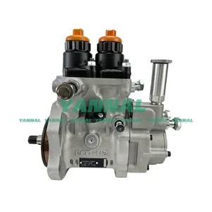
YANNAL PART 1 PC WA470-5 Fuel Injection Pump Assy Suitable for Komatsu Engine Part 094000-0380 6156-71-1110
YANNAL PART Product Name: Fuel Injection Pump Assy || Product Name: 094000-0380 6156-71-1110 || Application: Compatible for Komatsu WA470-5 || Warranty: 1 Year || Note: Please verify your part number before ordering, any problem please feel free to contact us, thanks.
YANNAL PART Product Name: Fuel Injection Pump Assy || Product Name: 094000-0380 6156-71-1110 || Application: Compatible for Komatsu WA470-5 || Warranty: 1 Year || Note: Please verify your part number before ordering, any problem please feel free to contact us, thanks.
You can express buy:
USD 710.11
19-05-2025
19-05-2025
diese Fuel Engine HP0 FUEL PUMP 094000-0380 094000-0381 094000-0382 094000-0383 6156-71-1110 6156711110
USD 1848
28-04-2025
28-04-2025
Fuel Injection Pump 094000-0380 6156-71-1112 for Komatsu Engine 6D125-3 Excavator PC400-7 PC450-7
USD 1098.25
28-04-2025
28-04-2025
WA470-5 Fuel Injection Pump Assy 094000-0380 6156-71-1110 For Komatsu Excavator Engine Parts
Components :
| 001. | PUMP ASSY, SUPPLY | 09400-00380 |
| 001. | PUMP ASSY, SUPPLY | 09400-00380 |
| 001. | PUMP ASSY, SUPPLY | 09400-00380 |
| 002. | OVERHAUL KIT, SUPP | 09404-00030 |
| 003. | BODY ASSY, SUPPLY | 09410-00343 |
| 004. | PUMP ASSY, FUEL FE | 09420-00301 |
Scheme ###:
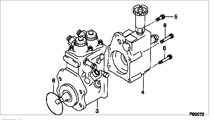
| 000. | [01] | 09400-00381 | PUMP ASSY, SUPPLY | 61567-11110 |
| 000. | [01] | 09400-00382 | PUMP ASSY, SUPPLY | 61567-11111 |
| 000. | [01] | 09400-00383 | PUMP ASSY, SUPPLY | 61567-11112 |
| 000-001. | [01] | 09404-00030 | OVERHAUL KIT, SUPP | |
| 003. | [01] | 09410-00344 | BODY ASSY, SUPPLY | |
| 004. | [01] | 09420-00301 | PUMP ASSY, FUEL FE | |
| 005. | [01] | 94904-43320 | BOLT | |
| 006. | [04] | 09644-90070 | BOLT, SOCKET | |
| 008. | [01] | 09408-60210 | O-RING, SUPPLY PUM |
Cross reference number
| Part num | Firm num | Firm | Name |
| 09400-00380 | PUMP ASSY, SUPPLY | ||
| 61567-11112 | KOMATSU | PUMP ASSY, SUPPLY | |
| 61567-11111 | KOMATSU | PUMP ASSY, SUPPLY | |
| 61567-11110 | KOMATSU | PUMP ASSY, SUPPLY |
Information:
Emergency Stopping
Emergency shutoff controls are for EMERGENCY use ONLY. DO NOT use emergency shutoff devices or controls for normal stopping procedure.
Make sure that any external system components that have been operating to support engine operation are secured after any stop.Emergency Stop Button
Emergency stop button, mounted on a junction box.Emergency stops may be made by pushing the Emergency Stop Button located on the junction box (if equipped). Both the button and the air inlet shutoff (if equipped) require resetting before the engine will start.Air Shutoff (If Equipped)
Some engines are equipped with an air shutoff, located between the aftercooler and the turbocharger. If equipped with an air shutoff lever, move the lever to the OFF position.Manual Stop Procedure
Stopping the engine immediately after it has been working under load, can result in overheating and accelerated wear of the engine components. Follow the stopping procedure, outlined below, to allow the engine to cool. Excessive temperatures in the turbocharger center housing will cause oil coking problems. Shutting the engine off without a cool down period does not allow the coolant temperature to stabilize, and may result in exhaust manifold cracking or leaking. Follow the stopping procedure outlined below to allow the engine to cool before shut down.
There may be several ways to shut off your engine. Make sure the shutoff procedures are understood. Use the following general guidelines for stopping the engine.1. Reduce engine speed to low idle.2. Shift into NEUTRAL.3. If the engine has been operated at low loads, run the engine at LOW IDLE for 30 seconds before stopping.If the engine has been operated at high load, increase engine speed to no more than 1/2 rated speed for three to five minutes to reduce and stabilize internal engine coolant and oil temperatures. Then reduce the engine speed to low idle before stopping.4. Check the marine transmission oil level while the engine is idling. Refer to the marine transmission OEM literature for lubrication maintenance recommendations.5. Follow your vessel's OEM instructions for stopping the engine with the pilot controls.A manual shutoff shaft is provided to override the governor control. The shaft can be used to move the fuel control linkage to the FUEL OFF position. The engine may be stopped by using the shaft and the mechanical governor control (if equipped).
Typical mechanical governor control.Move the mechanical governor control to the FUEL OFF position. Hold the control at the FUEL OFF position until the engine stops.After Stopping the Engine
Check the crankcase oil level. Maintain the oil level between the ADD and FULL marks on the dipstick.Repair any leaks, perform minor adjustments, tighten loose bolts, etc.Note the service hour meter reading. Perform periodic maintenance as instructed in the Maintenance Schedule.Fill the fuel tank to prevent accumulation of moisture in the fuel. Do not overfill.
Only use antifreeze/coolant mixtures recommended in the Cooling System Specifications of this manual. Failure to do so can cause engine damage.
Allow the engine to cool. Check the coolant level. Maintain the cooling system to 13 mm (1/2 inch) from bottom of the