Information holder & nozzle se
Rating:
Components :
| 001. | HOLDER & NOZZLE SE | 09350-06950 |
| 001. | HOLDER & NOZZLE SE | 09350-06950 |
Scheme ###:
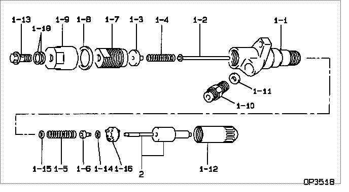
| 000. | [01] | 09350-06950 | HOLDER & NOZZLE SE | 23610-2120 |
| 000. | [01] | 09350-06950 | HOLDER & NOZZLE SE | S2361-02120 |
| 001. | [01] | 09310-06950 | HOLDER ASSY, NOZZL | S2363-02040-A |
| 001-001. | [01] | 09311-06950 | BODY SUB-ASSY, NOZ | |
| 001-002. | [01] | 09312-10580 | PIN, NOZZLE HOLDER | |
| 001-003. | [01] | 09312-50090 | BUSH, GUIDE | S2361-91090-A |
| 001-004. | [01] | 09312-70270 | SPRING, NOZZLE HOL | S2361-51270-A |
| 001-005. | [01] | 09312-70510 | SPRING, NOZZLE HOL | S2361-51350-A |
| 001-006. | [01] | 09312-80100 | SEAT, SPRING | |
| 001-007. | [01] | 09312-90150 | SCREW, CAP | |
| 001-008. | [01] | 09313-30100 | GASKET | S2366-11150-A |
| 001-009. | [01] | 09313-40191 | NUT, CAP | |
| 001-010. | [01] | 09315-10290 | CONNECTOR, NOZZLE | S2360-11130-A |
| 001-011. | [01] | 09315-80010 | GASKET, INLET CONN | S2362-11070-A |
| 001-012. | [01] | 09316-41600 | NUT, NOZZLE RETAIN | |
| 001-013. | [01] | 94918-00630 | SCREW, HOLLOW | S2283-51130-A |
| 001-013. | [01] | 09507-40012 | SCREW, HOLLOW OUTL | S2283-51570-A |
| 001-014. | [1C] | 09317-55390 | WASHER | S2288-56950-A |
| 001-014. | [1C] | 09317-55400 | WASHER | S2288-56960-A |
| 001-014. | [1C] | 09317-55410 | WASHER | S2288-56970-A |
| 001-014. | [1C] | 09317-55420 | WASHER | S2288-56980-A |
| 001-014. | [1C] | 09317-55430 | WASHER | S2288-56990-A |
| 001-014. | [1C] | 09317-55440 | WASHER | S2288-57000-A |
| 001-014. | [1C] | 09317-55450 | WASHER | S2288-57010-A |
| 001-014. | [1C] | 09317-55460 | WASHER | S2288-57020-A |
| 001-014. | [1C] | 09317-55470 | WASHER | S2288-57030-A |
| 001-014. | [1C] | 09317-55380 | WASHER | S2288-56940-A |
| 001-014. | [1C] | 09317-55370 | WASHER | S2288-56930-A |
| 001-014. | [1C] | 09317-55360 | WASHER | S2288-56920-A |
| 001-014. | [1C] | 09317-55270 | WASHER | S2288-56820-A |
| 001-014. | [1C] | 09317-55280 | WASHER | S2288-56830-A |
| 001-014. | [1C] | 09317-55290 | WASHER | S2288-56840-A |
| 001-014. | [1C] | 09317-55300 | WASHER | S2288-56850-A |
| 001-014. | [1C] | 09317-55310 | WASHER | S2288-56860-A |
| 001-014. | [1C] | 09317-55320 | WASHER | S2288-56870-A |
| 001-014. | [1C] | 09317-55330 | WASHER | S2288-56880-A |
| 001-014. | [1C] | 09317-55340 | WASHER | S2288-56900-A |
| 001-014. | [1C] | 09317-55350 | WASHER | S2288-56910-A |
| 001-015. | [1C] | 09317-55680 | WASHER | S2288-57250-A |
| 001-015. | [1C] | 09317-55670 | WASHER | S2288-57240-A |
| 001-015. | [1C] | 09317-55660 | WASHER | S2288-57230-A |
| 001-015. | [1C] | 09317-55650 | WASHER | S2288-57220-A |
| 001-015. | [1C] | 09317-55640 | WASHER | S2288-57210-A |
| 001-015. | [1C] | 09317-55690 | WASHER | S2288-57260-A |
| 001-015. | [1C] | 09317-55700 | WASHER | S2288-57270-A |
| 001-015. | [1C] | 09317-55710 | WASHER | S2288-57280-A |
| 001-015. | [1C] | 09317-55720 | WASHER | S2288-57290-A |
| 001-015. | [1C] | 09317-55730 | WASHER | S2288-57300-A |
| 001-015. | [1C] | 09317-55740 | WASHER | S2288-57310-A |
| 001-015. | [1C] | 09317-55750 | WASHER | S2288-57320-A |
| 001-015. | [1C] | 09317-55760 | WASHER | S2288-57330-A |
| 001-015. | [1C] | 09317-55630 | WASHER | S2288-57200-A |
| 001-015. | [1C] | 09317-55620 | WASHER | S2288-57190-A |
| 001-015. | [1C] | 09317-55610 | WASHER | S2288-57180-A |
| 001-015. | [1C] | 09317-55480 | WASHER | S2288-57040-A |
| 001-015. | [1C] | 09317-55490 | WASHER | S2288-57050-A |
| 001-015. | [1C] | 09317-55500 | WASHER | S2288-57060-A |
| 001-015. | [1C] | 09317-55510 | WASHER | S2288-57070-A |
| 001-015. | [1C] | 09317-55520 | WASHER | S2288-57080-A |
| 001-015. | [1C] | 09317-55530 | WASHER | S2288-57090-A |
| 001-015. | [1C] | 09317-55540 | WASHER | S2288-57100-A |
| 001-015. | [1C] | 09317-55550 | WASHER | S2288-57110-A |
| 001-015. | [1C] | 09317-55560 | WASHER | S2288-57120-A |
| 001-015. | [1C] | 09317-55570 | WASHER | S2288-57130-A |
| 001-015. | [1C] | 09317-55580 | WASHER | S2288-57140-A |
| 001-015. | [1C] | 09317-55590 | WASHER | S2288-57150-A |
| 001-015. | [1C] | 09317-55600 | WASHER | S2288-57160-A |
| 001-016. | [01] | 09322-00120 | PACKING SUB-ASSY, | S2361-71620-A |
| 001-018. | [02] | 94901-02640 | WASHER | S2284-71870-A |
| 002. | [01] | 09340-03180 | NOZZLE ASSY | S2365-01960-A |
Include in #3:
09350-06950
as HOLDER & NOZZLE SE
09350-06950
Cross reference number
| Part num | Firm num | Firm | Name |
| 09350-06950 | 23610-2120 | HOLDER & NOZZLE SE | |
| 23610-2120 | HINO | HOLDER & NOZZLE SE | |
| S2361-02120 | HINO | HOLDER & NOZZLE SE |
Information:
Starter, Preheat Structure And Operation
Starter
* This starter uses planetary gears as its reduction gearing mechanism.Alternator
<24V-35A> Circuit Diagram
Troubleshooting
Power And Charging
Engine Starting, Preheating and Stopping
#180 to #249 Relay, #250 to #349 Sensor, #750 to #859 Other
#187 Inspection of starter relay
* Perform continuity check and operation check, and if any fault is found, replace the relay.#231 Inspection of safety relay
* Measure the resistance values between terminals 2 and 3. * If the measured value deviates from the standard value, replace the relay.#262 Inspection of water temperature sensor
* Dip the sensor in a container filled with engine oil.* Raise the oil temperature to the specified one while stirring oil.* Measure the resistance between terminals 1 and 2. * If the measured value deviates from the standard value, replace the sensor. (See Gr14.)#764 Inspection of glow plug
* Measure the resistance value of glow plug as shown. * If the measured value deviates from the standard value, replace the glow plug. (See Gr11.)#930 Starter
* Before removing the starter, disconnect the (-) battery cable and insulate the cable and the (-) battery terminal with tape.* It is dangerous to leave the (-) battery cable connected since the battery cable is always present at terminal B.
Disassembly Sequence1 Stopper ring2 Pinion stopper3 Pinion4 Spring5 Magnetic switch6 Rear bracket7 Brush spring8 Brush (-)9 Brush holder10 Brush (+)11 Yoke12 Rear bearing13 Washer14 Armature15 Ball16 Cover17 Rubber packing18 Planetary gear19 Rubber packing20 Plate21 E-ring22 Gear shaft23 Washer24 Internal gear25 Overrunning clutch26 Lever27 Front bearing28 Oil seal29 Front bracketX: Non-reusable parts
* When the armature is removed, the ball may come out with it. Take care not to lose the ball.
* Do not remove the rear and front bearing unless defects are evident.* It is not necessary to remove the pinion when only the motor section needs to be disassembled for inspection, like when inspecting brushes and related parts.* Be sure to remove the pinion before disassembling any other parts. Assembly SequenceFollow the disassembly sequence in reverse.* Whenever the magnetic switch is replaced, the pinion gap must be adjusted.* The rubber packing is serviceable if any defect is not found.Service Standards (Unit: mm) Lubricant and/or Sealant Special Tools Work Before Disassembly Mating Mark: Rear bracket and yoke Disassembly Procedure Disassembly: Pinion* For removal of the pinion, the current must be supplied to the starter such that the pinion springs out.
* When the starter is energized, the pinion will spring out and rotate. Be careful not to touch it with your hands.* The magnetic switch may become very hot during inspections. Be careful when touching it.
* Do not energize the pull-in coil P for longer than 10 seconds, and do not energize the holding coil H for longer than 30 seconds. If these periods are exceeded, the coils may overheat and burn out.* To make the pinion spring out, be sure to energize the starter such that its parts are positioned correctly. If the starter is not energize and the lever is pulled to make the pinion come out, the front bracket and/or