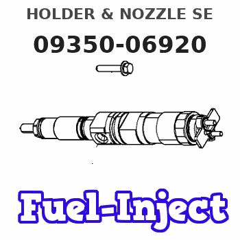
Information holder & nozzle se
Rating:
Components :
| 001. | HOLDER & NOZZLE SE | 09350-06920 |
Scheme ###:

| 000. | [01] | 09350-06920 | HOLDER & NOZZLE SE | 23600-54190 |
| 001. | [01] | 09310-06920 | HOLDER ASSY, NOZZL | 23610-54190 |
| 001-001. | [01] | 09311-06920 | BODY SUB-ASSY, NOZ | 23626-54190 |
| 001-002. | [01] | 09312-10380 | PIN, NOZZLE HOLDER | 23619-64010 |
| 001-003. | [01] | 09312-70460 | SPRING, NOZZLE HOL | 23618-54730 |
| 001-004. | [01] | 09316-41351 | NUT, NOZZLE RETAIN | 23624-55010 |
| 001-004. | [01] | 09316-41321 | NUT, NOZZLE RETAIN | 23624-55050 |
| 001-005. | [01] | 09317-40090 | DISTANCE PIECE | 23629-54080 |
| 001-006. | [1C] | 09317-51980 | WASHER | 23634-64011 |
| 001-006. | [1C] | 09317-51970 | WASHER | 23634-64010 |
| 001-006. | [1C] | 09317-51960 | WASHER | 23633-64019 |
| 001-006. | [1C] | 09317-51950 | WASHER | 23633-64018 |
| 001-006. | [1C] | 09317-51940 | WASHER | 23633-64017 |
| 001-006. | [1C] | 09317-51930 | WASHER | 23633-64016 |
| 001-006. | [1C] | 09317-51920 | WASHER | 23633-64015 |
| 001-006. | [1C] | 09317-51910 | WASHER | 23633-64014 |
| 001-006. | [1C] | 09317-51900 | WASHER | 23633-64013 |
| 001-006. | [1C] | 09317-51990 | WASHER | 23634-64012 |
| 001-006. | [1C] | 09317-52000 | WASHER | 23634-64013 |
| 001-006. | [1C] | 09317-52090 | WASHER | 23635-64012 |
| 001-006. | [1C] | 09317-52080 | WASHER | 23635-64011 |
| 001-006. | [1C] | 09317-52070 | WASHER | 23635-64010 |
| 001-006. | [1C] | 09317-52060 | WASHER | 23634-64019 |
| 001-006. | [1C] | 09317-52050 | WASHER | 23634-64018 |
| 001-006. | [1C] | 09317-52040 | WASHER | 23634-64017 |
| 001-006. | [1C] | 09317-52030 | WASHER | 23634-64016 |
| 001-006. | [1C] | 09317-52020 | WASHER | 23634-64015 |
| 001-006. | [1C] | 09317-52010 | WASHER | 23634-64014 |
| 001-006. | [1C] | 09317-51890 | WASHER | 23633-64012 |
| 001-006. | [1C] | 09317-51880 | WASHER | 23633-64011 |
| 001-006. | [1C] | 09317-51870 | WASHER | 23633-64010 |
| 001-006. | [1C] | 09317-51750 | WASHER | 23631-64018 |
| 001-006. | [1C] | 09317-51740 | WASHER | 23631-64017 |
| 001-006. | [1C] | 09317-51730 | WASHER | 23631-64016 |
| 001-006. | [1C] | 09317-51720 | WASHER | 23631-64015 |
| 001-006. | [1C] | 09317-51710 | WASHER | 23631-64014 |
| 001-006. | [1C] | 09317-51700 | WASHER | 23631-64013 |
| 001-006. | [1C] | 09317-51690 | WASHER | 23631-64012 |
| 001-006. | [1C] | 09317-51680 | WASHER | 23631-64011 |
| 001-006. | [1C] | 09317-51670 | WASHER | 23631-64010 |
| 001-006. | [1C] | 09317-51760 | WASHER | 23631-64019 |
| 001-006. | [1C] | 09317-51770 | WASHER | 23632-64010 |
| 001-006. | [1C] | 09317-51860 | WASHER | 23632-64019 |
| 001-006. | [1C] | 09317-51850 | WASHER | 23632-64018 |
| 001-006. | [1C] | 09317-51840 | WASHER | 23632-64017 |
| 001-006. | [1C] | 09317-51830 | WASHER | 23632-64016 |
| 001-006. | [1C] | 09317-51820 | WASHER | 23632-64015 |
| 001-006. | [1C] | 09317-51810 | WASHER | 23632-64014 |
| 001-006. | [1C] | 09317-51800 | WASHER | 23632-64013 |
| 001-006. | [1C] | 09317-51790 | WASHER | 23632-64012 |
| 001-006. | [1C] | 09317-51780 | WASHER | 23632-64011 |
| 001-007. | [01] | 09324-50140 | WASHER | 23654-64010 |
| 001-009. | [01] | 94905-04260 | NUT, HEXAGON | 23628-64010 |
| 002. | [01] | 09340-06960 | NOZZLE ASSY | 23620-54190 |
Include in #3:
09350-06920
as HOLDER & NOZZLE SE
Include as Nozzle:
Cross reference number
| Part num | Firm num | Firm | Name |
| 09350-06920 | 23600-5419 | HOLDER & NOZZLE SE | |
| 23600-54190 | TOYOTA | HOLDER & NOZZLE SE |
Information:
Remarks
Output and torque represent performance of run-in engine operating under the standard ambient conditions and accessories specified below. Structure And Operation
Exploded View
Cylinder Head and Cylinder Head Gasket
Cylinder head
* The cylinder head has swirl chambers each with a combustion jet that directs the flow of combustion gas from the swirl chamber to the main combustion chamber.* The combustion jet is held against rotation by a tablet.* The cylinder head is cooled by coolant flowing through the water jackets formed in it. Water directors are installed at the bottom of the cylinder head to direct coolant flow.* The intake ports and the exhaust ports are arranged alternately on the right side of the cylinder head (counter-flow type)* The cylinder head bolts must be tightened according to the specified procedure.Cylinder head gasket
* Select and use a cylinder head gasket of a thickness that can accommodate the piston projection.* The size (thickness) class of the gasket can be identified by the shape of the notches cut on the edge of each gasket.Valve Mechanism and Timing Chain
Valve Mechanism
* The camshaft is driven by the timing chain. Camshaft journals are rotatably held against the cylinder head by camshaft caps.* A lifter shim is installed between the camshaft and each valve lifter. Valve clearance is adjusted by changing the thickness of the shim.* The valve springs are unequally pitched springs, each having a paint mark on one end to indicate the top when it is installed.Timing Chain
* The timing chain is an endless chain with 98 links that connects the cam sprocket and the idler sprocket.* The timing chain has mark link plates at two locations that indicate the position at which the crankshaft and the camshaft should take when the chain is installed. There are two plates at the first location and one plate at the second location. The first location (two-mark-link location) must be aligned with the mating mark " O " on the cam sprocket and the second location (one-mark-link location) must be aligned with the mating mark " O " on the idler sprocket.* The guide plate has an oil jet that sprays engine oil on the timing chain through the injection hole.* The tensioner gives tension to the timing chain. The tensioner has a plunger with a built-in spring.* When the tensioner is installed in position, the plunger pushes the tension lever and the tension lever, in turn; pushes the chain. The timing chain is tensioned automatically by a force determined by the tension of the plunger spring.* After the timing chain is adequately tensioned, the plunger is locked in place by a cam provided in the tensioner, which prevents accidental deflection of the timing chain while the engine is running. Do not crank the engine in the reverse direction after installing the tensioner, as this will apply undue forces to the plunger and may cause such undesirable consequences as cam being over ridden by the plunger.Timing Gears
* Each timing gear has mating mark(s) "1" or "5" on the side