Information holder & nozzle se
Rating:
Components :
| 001. | HOLDER & NOZZLE SE | 09350-06730 |
| 002. | HOLDER & NOZZLE SE | 09350-06710 |
Scheme ###:
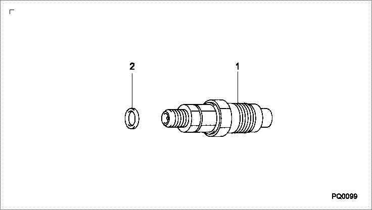
| 000. | [01] | 09350-06731 | HOLDER & NOZZLE SE | 23600-59266 |
| 001. | [01] | 09350-06711 | HOLDER & NOZZLE SE | 23600-54171 |
| 002. | [01] | 09313-30560 | GASKET | 11177-54020 |
Cross reference number
| Part num | Firm num | Firm | Name |
| 09350-06730 | HOLDER & NOZZLE SE | ||
| 23600-59266 | TOYOTA | HOLDER & NOZZLE SE |
Information:
Rework Procedure
This procedure is only required when utilizing the 444-2472 Bracket As or 444-2473 Bracket As, the former 222-6953 Valve Cover Bases, and the new stamped steel valve covers. Disregard if using 442-5727 Valve Cover Base.The preferred method to correct this issue is to remove the former 222-6953 Valve Cover Base and install the current 442-5727 Valve Cover Base. This valve cover base removes the need for the 444-2472 Bracket As and 444-2473 Bracket As.The alternative method is to modify the 444-2472 Bracket As or 444-2473 Bracket As to be used with the 222-6953 Valve Mechanism Cover Base and stamped steel valve cover.Note:
Illustration 1 g06088172
Bracket assemblies view
(1) 444-2472 Bracket As
(2) 444-2473 Bracket As
Illustration 2 g06088191
Side view of the bracket.
(3) Button portion
(4) Weld stud
Illustration 3 g06088192
Top view of the bracket.
The illustration above shows the location of the material that will need to be removed from the button of the bracket assemblies.
Illustration 4 g06088194
Side view of the bracket.
Illustration 5 g06088195
View of the bracket after modification.
Remove 4 mm (0.16 in) from the button on the bracket as shown in Illustration 4.
Once the additional material has been removed from the modified bracket, fit the valve cover to ensure that proper clearance has been created allowing sealing of valve cover PIP seal. Install and torque the valve cover using the appropriate procedure from the Disassembly and Assembly manual.
Illustration 6 g06088196
Impression made by bracket assemblies that contact the valve cover.
Remove the valve cover and inspect the mating surface to see if any contact marks are present as shown in Illustration 6. If contact marks are present, extra material of the button will need to be removed for clearance.