Information holder & nozzle se
Rating:
Components :
| 001. | HOLDER & NOZZLE SE | 09350-05660 |
Scheme ###:
| 000. | [01] | 09350-05660 | HOLDER & NOZZLE SE | ME076427 |
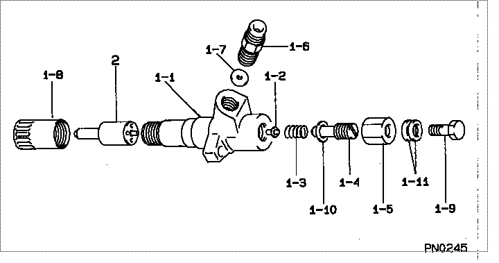
| 001. | [01] | 09310-05660 | HOLDER ASSY, NOZZL | ME736144 |
| 001-001. | [01] | 09311-05660 | BODY SUB-ASSY, NOZ | |
| 001-002. | [01] | 09312-10330 | PIN, NOZZLE HOLDER | ME703615 |
| 001-003. | [01] | 09312-70270 | SPRING, NOZZLE HOL | ME703616 |
| 001-004. | [01] | 09313-10200 | SCREW, ADJUST | ME703617 |
| 001-005. | [01] | 09313-40150 | NUT, CAP | ME022310 |
| 001-005. | [01] | 09313-40290 | NUT, CAP | ME703618 |
| 001-006. | [01] | 09315-10380 | CONNECTOR, NOZZLE | ME703265 |
| 001-007. | [01] | 09315-80010 | GASKET, INLET CONN | MM500889 |
| 001-008. | [01] | 09316-41400 | NUT, NOZZLE RETAIN | ME728359 |
| 001-009. | [01] | 09316-60091 | SCREW, HOLLOW | ME703657 |
| 001-010. | [01] | 09324-50052 | WASHER | MM501731 |
| 001-011. | [02] | 94901-81020 | WASHER, COPPER PLA | ME022309 |
| 002. | [01] | 09340-02330 | NOZZLE ASSY | ME728106 |
Include in #3:
09350-05660
as HOLDER & NOZZLE SE
Include as Nozzle:
Cross reference number
| Part num | Firm num | Firm | Name |
| 09350-05660 | ME076427 | HOLDER & NOZZLE SE | |
| ME076427 | MITSUBISHI | HOLDER & NOZZLE SE |
Information:
Table 1
Required Sleeve Part Numbers
S.No Qty (1) Qty (2) New Part Number Part Name Sleeve color Volume / Injector
1 6 6 449-3816 Locknut Not applicable 0.25 cc (0.02 cubic inch)
2 26 32 420-0939 Spacer Red 0.500 cc (0.030 cubic inch)
3 7 7 420-0940 Spacer Silver 0.75 cc (0.05 cubic inch)
4 0 0 420-0941 Spacer Gold 1.0 cc (0.1 cubic inch)
5 12 12 420-0942 Spacer Green 1.25 cc (0.08 cubic inch)
6 0 0 513-1992 Sleeve Purple (3) 2.5 cc (0.15 cubic inch)
(1) For MD6250 Rotary Drills
(2) For MD6310 Rotary Drills
(3) To be used only on SLV-XL (Jack Casing injectors)
Do not operate or work on this product unless you have read and understood the instruction and warnings in the relevant Operation and Maintenance Manuals and relevant service literature. Failure to follow the instructions or heed the warnings could result in injury or death. Proper care is your responsibility.
General Procedure to Replace Sleeves
Illustration 1 g06357787
(A) Cap
(B) Screw
Remove cap (A) and screw (B). Save the parts.
Illustration 2 g06357788
(C) Sleeve (Silver)
(D) Sleeve (Red)
Remove sleeve (C). Discard the sleeves. Replace sleeve (C) with sleeve (D).
Illustration 3 g06357789
(A) Cap
(B) Screw
Install screw (B) and Cap (A) which were saved in Step 1.Note: Follow the same procedure to replace sleeves in all the grease injectors on the machine.Replace the injector bank sleeve sizes as specified in the instructions below:Grease Injector Location Identification for MD6250 Rotary Drills
The following are the grease injector locations in 503-7710 Requirements for manual or premium lube:Front Left Bank - Lube Points and Locations
Illustration 4 g06355819
Front left bank - lube points
(A) Front Left Jack Casing
(B) Front Left Jack Casing
(C) Front Left Jack Casing
(D) Front Right Jack Casing
(E) Front Right Jack Casing
(F) Front Right Jack Casing
(G) Center Pin on Equalizer Bar
(H) Right Tram Equalizer Pin
(J) Left Tram Equalizer Pin
Table 2
Front Left Bank
Item Description Sleeve color
A Front Left Jack Casing Green
B Front Left Jack Casing Green
C Front Left Jack Casing Green
D Front Right Jack Casing Green
E Front Right Jack Casing Green
F Front Right Jack Casing Green
G Center Pin on Equalizer Bar Silver
H Right Tram Equalizer Pin Silver
J