Information holder & nozzle se
Rating:
Components :
| 001. | HOLDER & NOZZLE SE | 09350-05620 |
Scheme ###:
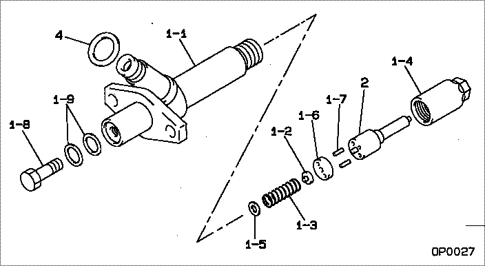
| 000. | [01] | 09350-05620 | HOLDER & NOZZLE SE | 23600-87316-000 |
| 001. | [01] | 09310-05620 | HOLDER ASSY, NOZZL | 23610-87316-000 |
| 001-001. | [01] | 09311-05620 | BODY SUB-ASSY, NOZ | 23626-87316-000 |
| 001-002. | [01] | 09312-10480 | PIN, NOZZLE HOLDER | 23619-58030-000 |
| 001-003. | [01] | 09312-70410 | SPRING, NOZZLE HOL | 23618-58030-000 |
| 001-004. | [01] | 09316-41020 | NUT, NOZZLE RETAIN | 23624-58010-000 |
| 001-005. | [1C] | 09317-52570 | WASHER | 23633-58014-000 |
| 001-005. | [1C] | 09317-52560 | WASHER | 23633-58013-000 |
| 001-005. | [1C] | 09317-52530 | WASHER | 23633-58012-000 |
| 001-005. | [1C] | 09317-52460 | WASHER | 23633-58011-000 |
| 001-005. | [1C] | 09317-52450 | WASHER | 23633-58010-000 |
| 001-005. | [1C] | 09317-52440 | WASHER | 23632-58019-000 |
| 001-005. | [1C] | 09317-52430 | WASHER | 23632-58018-000 |
| 001-005. | [1C] | 09317-52580 | WASHER | 23633-58015-000 |
| 001-005. | [1C] | 09317-52590 | WASHER | 23633-58016-000 |
| 001-005. | [1C] | 09317-52600 | WASHER | 23633-58017-000 |
| 001-005. | [1C] | 09317-52610 | WASHER | 23633-58018-000 |
| 001-005. | [1C] | 09317-52620 | WASHER | 23633-58019-000 |
| 001-005. | [1C] | 09317-52630 | WASHER | 23634-58010-000 |
| 001-005. | [1C] | 09317-52640 | WASHER | 23634-58011-000 |
| 001-005. | [1C] | 09317-52650 | WASHER | 23634-58012-000 |
| 001-005. | [1C] | 09317-52660 | WASHER | 23634-58013-000 |
| 001-005. | [1C] | 09317-52420 | WASHER | 23632-58017-000 |
| 001-005. | [1C] | 09317-52340 | WASHER | 23632-58016-000 |
| 001-005. | [1C] | 09317-52180 | WASHER | 23631-58010-000 |
| 001-005. | [1C] | 09317-52190 | WASHER | 23631-58011-000 |
| 001-005. | [1C] | 09317-52200 | WASHER | 23631-58012-000 |
| 001-005. | [1C] | 09317-52210 | WASHER | 23631-58013-000 |
| 001-005. | [1C] | 09317-52220 | WASHER | 23631-58014-000 |
| 001-005. | [1C] | 09317-52230 | WASHER | 23631-58015-000 |
| 001-005. | [1C] | 09317-52240 | WASHER | 23631-58016-000 |
| 001-005. | [1C] | 09317-52250 | WASHER | 23631-58017-000 |
| 001-005. | [1C] | 09317-52260 | WASHER | 23631-58018-000 |
| 001-005. | [1C] | 09317-52330 | WASHER | 23632-58015-000 |
| 001-005. | [1C] | 09317-52320 | WASHER | 23632-58014-000 |
| 001-005. | [1C] | 09317-52310 | WASHER | 23632-58013-000 |
| 001-005. | [1C] | 09317-52300 | WASHER | 23632-58012-000 |
| 001-005. | [1C] | 09317-52290 | WASHER | 23632-58011-000 |
| 001-005. | [1C] | 09317-52280 | WASHER | 23632-58010-000 |
| 001-005. | [1C] | 09317-52270 | WASHER | 23631-58019-000 |
| 001-006. | [01] | 09322-10150 | PACKING, TIP | 23659-58030-000 |
| 001-007. | [02] | 94908-23160 | PIN, STRAIGHT | 90099-08096-000 |
| 001-008. | [01] | 09316-60080 | SCREW, HOLLOW | 23625-58230-000 |
| 001-009. | [02] | 94901-81020 | WASHER, COPPER PLA | 90201-08106-000 |
| 002. | [01] | 09340-06210 | NOZZLE ASSY | 23620-87313-000 |
| 004. | [01] | 09313-30200 | GASKET |
Include in #3:
09350-05620
as HOLDER & NOZZLE SE
Include as Nozzle:
0960009130
as Nozzle
Cross reference number
| Part num | Firm num | Firm | Name |
| 09350-05620 | 23600-8731 | HOLDER & NOZZLE SE | |
| 23600-87316-000 | DAIHATSU | HOLDER & NOZZLE SE |
Information:
Introduction
Keep all parts clean from contaminants.Contaminants may cause rapid wear and shortened component life.
Care must be taken to ensure that fluids are contained during performance of inspection, maintenance, testing, adjusting and repair of the product. Be prepared to collect the fluid with suitable containers before opening any compartment or disassembling any component containing fluids.Refer to Special Publication, NENG2500, "Caterpillar Dealer Service Tool Catalog" for tools and supplies suitable to collect and contain fluids on Caterpillar products.Dispose of all fluids according to local regulations and mandates.
This Special Instruction addresses the necessary parts and the necessary information for the removal of the plugs for the outlet check valves and the installation of the plugs for the outlet check valves on a CR350 fuel pump.There has been an improvement to the check valve assembly. The addition of a ball stud has been made to the assembly for improved durability.Disassembly
The following tools are needed: torque wrench, 16 millimeter socket or wrench, cotton swabs, rubbing alcohol, rubber gloves, small magnet, flashlight, plastic spray bottle and molykote or white lithium greaseThe following parts are supplied: two plugs for the outlet check valves, two outlet check valves, two springs and two ball studs
Ensure the proper cleanliness of hands and all parts before you begin the service procedure.
Check the engine serial number in order to ensure that the engine is correct for the service letter.
Steam clean the area that surrounds the plug for the outlet check valve or clean the area around the plug for the outlet check valve by flushing with rubbing alcohol.
The area must be cleaned with a towel that is soaked with alcohol in order to remove any other debris.
Inspect the area that is surrounding the plug for the outlet check valve in order to ensure that no debris is present.
Illustration 1 g01618509
Using a clean 16 millimeter socket or a wrench remove the plug for the outlet check valve.
Carefully remove the plug from the pump head. The spring is removed with the plug.
If the outlet check valve remains in the head, remove the check valve with the clean magnet.
Clean the threads and the area around the plug.Note: Soak the cotton swab with alcohol and insert the cotton swab into the threaded area. Use a counterclockwise rotation to clean the threaded area. Clean the spot face around the plug bore with a cotton swab that is soaked in alcohol. Clean the spot face around the plug bore in a counterclockwise rotation.
Illustration 2 g01626597
(1) Sealing surface of the pump bore
Look inside the pump bore in order to ensure that no debris that includes the debris from the cotton swab is on the sealing surface.
Repeat until the cotton swab is free of debris.
Illustration 3 g01618506
Assembly
Once parts have been removed, clean hands and put on clean rubber gloves.
When the parts are being installed in the pump, flush all the new parts with alcohol in order to ensure that no debris is on the parts.
Use a clean finger to apply clean molykote or white lithium grease to the surface that is