Information holder & nozzle se
Rating:
Components :
| 001. | HOLDER & NOZZLE SE | 09350-05320 |
Scheme ###:
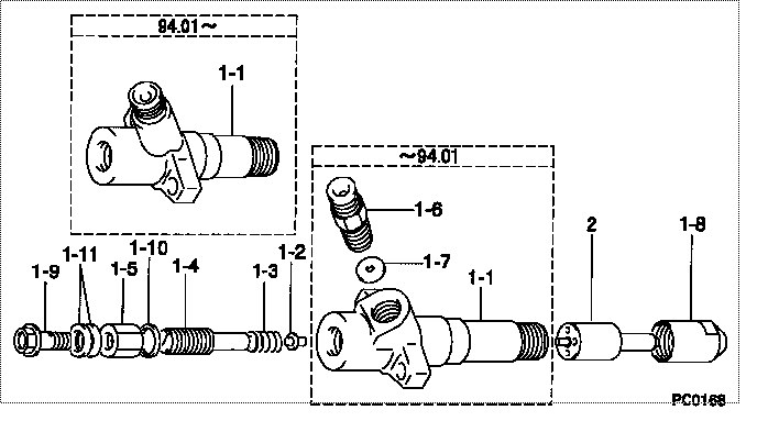
| 000. | [01] | 09350-05320 | HOLDER & NOZZLE SE | 23610-1900 |
| 000. | [01] | 09350-05320 | HOLDER & NOZZLE SE | S2361-01900 |
| 001. | [01] | 09310-05320 | HOLDER ASSY, NOZZL | 23630-1840A |
| 001. | [01] | 09310-05580 | HOLDER ASSY, NOZZL | |
| 001-001. | [01] | 09311-05320 | BODY SUB-ASSY, NOZ | |
| 001-002. | [01] | 09312-10330 | PIN, NOZZLE HOLDER | 23616-1030A |
| 001-003. | [01] | 09312-70270 | SPRING, NOZZLE HOL | 23615-1270A |
| 001-004. | [01] | 09313-10200 | SCREW, ADJUST | 23614-1060A |
| 001-005. | [01] | 09313-40150 | NUT, CAP | 23623-1200 |
| 001-005. | [01] | 09313-40270 | NUT, CAP | 23623-1200 |
| 001-006. | [01] | 09315-10420 | CONNECTOR, NOZZLE | 23633-1600A |
| 001-007. | [01] | 09315-80010 | GASKET, INLET CONN | 22835-1130A |
| 001-008. | [01] | 09316-41470 | NUT, NOZZLE RETAIN | 23633-1600A |
| 001-009. | [01] | 94918-00630 | SCREW, HOLLOW | 22835-1130A |
| 001-010. | [01] | 09324-50052 | WASHER | 22847-1290A |
| 001-011. | [02] | 94901-02640 | WASHER | 22847-1870A |
| 002. | [01] | 09340-02720 | NOZZLE ASSY | 23650-1780A |
Include in #3:
09350-05320
as HOLDER & NOZZLE SE
09350-05320
Include as Nozzle:
Cross reference number
| Part num | Firm num | Firm | Name |
| 09350-05320 | 23610-1900 | HOLDER & NOZZLE SE | |
| 23610-1900 | HINO | HOLDER & NOZZLE SE | |
| S2361-01900 | HINO | HOLDER & NOZZLE SE |
Information:
Introduction
Do not perform any procedure in this Special Instruction until you have read the information and you understand the information.If the crankshaft, gear case and/or crank gear are replaced, it is necessary to perform the injection timing correction procedure. The following steps show how to calculate/determine the new injection timing by measuring angular deviation between the crankshaft TDC and Crank Position sensor detected TDC.Note: Once complete the engine ecm must be reprogrammed with the new injection timing value. Follow all Steps below.Procedure
Illustration 1 g06220080
(1) TC Mark (Flywheel Housing)
(2) TC Mark (Flywheel)
Remove valve cover, injector, and rocker arm. Bring the piston of cylinder 4 to TDC.
Illustration 2 g06220082
(3) Dial Gauge
(4) Valve
(5) O-ring
Remove the #4 exhaust valve bridge arm and valve spring. Insert a small O-ring (5) so the valve (4) does not fall into the cylinder.
Set the dial gauge (3) on the tip of the valve (4).
Illustration 3 g06220083
(6) Tri-sqaure
(7) Flywheel Housing
(8) Flywheel
Illustration 4 g06220087
(7) Flywheel Housing
(8) Flywheel
(9) Reference Line
Turn the flywheel counterclockwise and measure the position where the tip of the valve is highest.
Stop the flywheel at the position where the tip of the valve is the highest. Put a tri-sqaure (6) on the flywheel housing (7) and the flywheel (8) and draw a reference line (9).Do not drop the valve (4) into the cylinder. When measuring the highest position of the tip of the valve do not rotate the flywheel clockwise. If you go past the highest point of the valve, back up the flywheel slightly and measure the highest point of the valve. The reference line (9) indicates the TDC of the crankshaft.
Illustration 5 g06220092
(10) Tester
(11) Crankshaft Position Sensor
Illustration 6 g06220095
(11) Crankshaft Position Sensor
(12) Ground Terminal
(13) Output Terminal
Connect the engine harness and the main switch. Connect battery.Attach the tester (10) to the output terminal (13) and the ground terminal (12) of the crankshaft position sensor (11). Turn the main switch "ON". Turn the flywheel and make sure that the voltage of the crankshaft position sensor goes from 0→ 5 V or 5 → 0 V.
Illustration 7 g06220100
(14) Pulsar Gear
(15) 14th Tooth
(16) Missing Teeth
Rotate the flywheel and align the crankshaft position sensor to the part of the pulsar gear (14) that is missing teeth (16). The 14th tooth (15) from the missing teeth is the standard. Slowly turn the flywheel counterclockwise and stop the flywheel at the point where the needle of the tester changes momentarily from 0→ 5 V, the 14th tooth. That point is where the crankshaft position sensor detects TDC.
Illustration 8 g06220101
(17) Crankshaft TDC
(18) Detection Point of Crankshaft Position Sensor TDC
Illustration 9 g06220104
(19) Interval
Set the tri-square (6) on the reference line (9) on the flywheel housing side and mark the detection point of the crankshaft position sensor TDC (18) on the flywheel.
Measure the interval (19) between the crankshaft TDC (17) and the detection point of the crankshaft position sensor TDC (18).
Calculation of the fuel injection timing correction 1 mm (0.039 inch): 0.342°.Corrected angle = 0.342° X actual interval.
Overwrite the injection timing correction value on the engine ecm registration website refer to REHS9707, "Registering