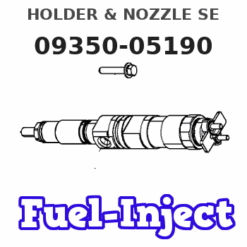
Information holder & nozzle se
Rating:
Compare Prices: .
As an associate, we earn commssions on qualifying purchases through the links below

4PCS Fuel Injector Assy Compatible With 1PZ/2C-TL 093500-4740 23600-19015 093500-5430 23600-17040 093500-5190 23600-69065 093500-4460
LJBljf Long service life, reducing maintenance costs. || Smooth acceleration, precise fuel injection, and efficient atomization. || Improve fuel efficiency, make fuel more abundant, and achieve fuel efficiency. || Boosting power, fuel-efficient and durable, resistant to high temperatures and corrosion. || 4PCS Fuel Injector Assy Compatible With 1PZ/2C-TL 093500-4740 23600-19015 093500-5430 23600-17040 093500-5190 23600-69065 093500-4460
LJBljf Long service life, reducing maintenance costs. || Smooth acceleration, precise fuel injection, and efficient atomization. || Improve fuel efficiency, make fuel more abundant, and achieve fuel efficiency. || Boosting power, fuel-efficient and durable, resistant to high temperatures and corrosion. || 4PCS Fuel Injector Assy Compatible With 1PZ/2C-TL 093500-4740 23600-19015 093500-5430 23600-17040 093500-5190 23600-69065 093500-4460
Components :
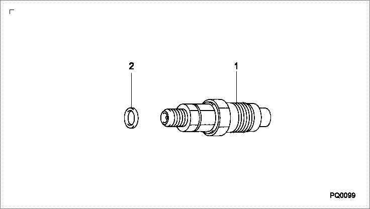
| 001. | HOLDER & NOZZLE SE | 09350-05190 |
| 001. | HOLDER & NOZZLE SE | 09350-05190 |
| 001. | HOLDER & NOZZLE SE | 09350-05190 |
| 001. | HOLDER & NOZZLE SE | 09350-05190 |
| 002. | HOLDER & NOZZLE SE | 09350-05080 |
| 002. | HOLDER & NOZZLE SE | 09350-05080 |
Scheme ###:
| 000. | [01] | 09350-05190 | HOLDER & NOZZLE SE | 23600-69065-000 |
| 000. | [01] | 09350-05190 | HOLDER & NOZZLE SE | 23600-69065 |
| 001. | [01] | 09350-05080 | HOLDER & NOZZLE SE | 23600-64070-000 |
| 001. | [01] | 09350-05080 | HOLDER & NOZZLE SE | 23600-64070 |
| 002. | [01] | 09313-30150 | GASKET | 11177-64010-000 |
| 002. | [01] | 09313-30150 | GASKET | 11177-64010 |
Include in #3:
09350-05190
as HOLDER & NOZZLE SE
09350-05190
Include as Nozzle:
0960007350
as Nozzle
Cross reference number
| Part num | Firm num | Firm | Name |
| 09350-05190 | 23600-6906 | HOLDER & NOZZLE SE | |
| 23600-69065-000 | DAIHATSU | HOLDER & NOZZLE SE | |
| 23600-69065 | TOYOTA | HOLDER & NOZZLE SE |
Information:
Service Tool
Illustration 1 g01250874
4C-6585 Indicator Group (1) Hand tool for tightening gauge connectionProcedure for Checking Cylinder Pressure
Take the readings for cylinder pressure at the rated speed and at the rated load in order to obtain the peak cylinder pressure for a specific rating.Readings for cylinder pressure can also be taken at a light load condition or at a no-load condition. These pressure readings can be used as a baseline for a comparison at a later date. For a valid comparison, pressure measurements that are taken at a later date must duplicate the initial load conditions.
Illustration 2 g01250892
(2) Cylinder pressure valve (Kiene valve) (3) Valve stem (4) Cap
Remove cap (4) from valve (2) .
Fluids may escape from the cylinder pressure valves at high velocity during this procedure and cause personal injury. Always stay clear and keep personnel away from the cylinder pressure valves during this procedure.
Stand to the side of the valve and open valve stem (3) approximately 90° (1/4 turn) counterclockwise. Close valve stem (3). This will blow any foreign debris out of the valve.
Illustration 3 g01250917
(5) 4C-9736 Pressure Gauge (6) 4C-9737 Gauge connection
Install the 4C-6585 Indicator group on the valve. Use tool (1) that is provided in the indicator group in order to tighten gauge connection (6) to a torque of 17 3 N m (12 2 lb ft). Do not overtighten the gauge connection.
Open valve stem (3) by approximately 540° (1 1/2 turn) counterclockwise. Document the reading on pressure gauge (5) and close valve stem (3). Tighten the valve stem to a torque of 24 3 N m (18 2 lb ft). Do not overtighten the valve stem.
Use the hand tool that is provided in the indicator group in order to loosen the gauge connection. Remove the 4C-6585 Indicator Group .
Install cap (4). Tighten to a torque of 17 3 N m (12 2 lb ft). Do not overtighten the cap.