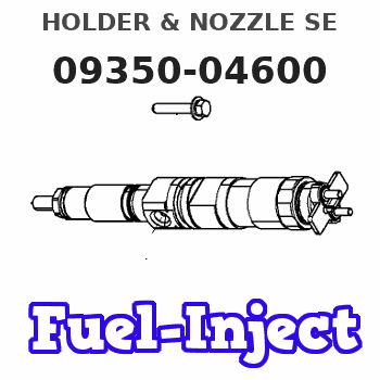
Information holder & nozzle se
Rating:
Components :
| 001. | HOLDER & NOZZLE SE | 09350-04600 |
Scheme ###:
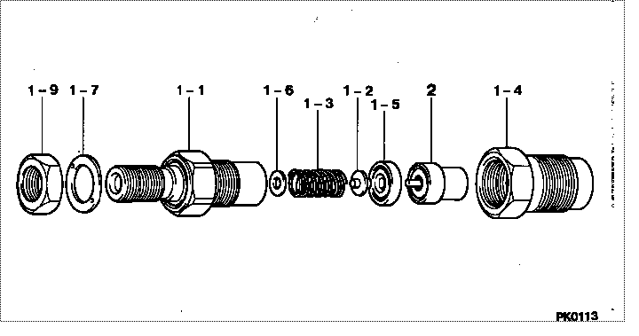
| 000. | [01] | 09350-04600 | HOLDER & NOZZLE SE | 23600-55060 |
| 001. | [01] | 09310-04600 | HOLDER ASSY, NOZZL | 23610-55060 |
| 001-001. | [01] | 09311-04600 | BODY SUB-ASSY, NOZ | 23626-55060 |
| 001-002. | [01] | 09312-10380 | PIN, NOZZLE HOLDER | 23619-64010 |
| 001-003. | [01] | 09312-70310 | SPRING, NOZZLE HOL | 23618-64010 |
| 001-004. | [01] | 09316-41351 | NUT, NOZZLE RETAIN | 23624-55010 |
| 001-004. | [01] | 09316-41321 | NUT, NOZZLE RETAIN | 23624-55050 |
| 001-005. | [01] | 09317-40070 | DISTANCE PIECE | 23629-64010 |
| 001-006. | [1C] | 09317-51980 | WASHER | 23634-64011 |
| 001-006. | [1C] | 09317-51970 | WASHER | 23634-64010 |
| 001-006. | [1C] | 09317-51960 | WASHER | 23633-64019 |
| 001-006. | [1C] | 09317-51950 | WASHER | 23633-64018 |
| 001-006. | [1C] | 09317-51940 | WASHER | 23633-64017 |
| 001-006. | [1C] | 09317-51930 | WASHER | 23633-64016 |
| 001-006. | [1C] | 09317-51920 | WASHER | 23633-64015 |
| 001-006. | [1C] | 09317-51910 | WASHER | 23633-64014 |
| 001-006. | [1C] | 09317-51900 | WASHER | 23633-64013 |
| 001-006. | [1C] | 09317-51990 | WASHER | 23634-64012 |
| 001-006. | [1C] | 09317-52000 | WASHER | 23634-64013 |
| 001-006. | [1C] | 09317-54050 | WASHER | |
| 001-006. | [1C] | 09317-54040 | WASHER | |
| 001-006. | [1C] | 09317-54030 | WASHER | |
| 001-006. | [1C] | 09317-54020 | WASHER | |
| 001-006. | [1C] | 09317-54010 | WASHER | |
| 001-006. | [1C] | 09317-54000 | WASHER | |
| 001-006. | [1C] | 09317-53990 | WASHER | |
| 001-006. | [1C] | 09317-53980 | WASHER | |
| 001-006. | [1C] | 09317-52010 | WASHER | 23634-64014 |
| 001-006. | [1C] | 09317-51890 | WASHER | 23633-64012 |
| 001-006. | [1C] | 09317-51880 | WASHER | 23633-64011 |
| 001-006. | [1C] | 09317-51870 | WASHER | 23633-64010 |
| 001-006. | [1C] | 09317-51750 | WASHER | 23631-64018 |
| 001-006. | [1C] | 09317-51740 | WASHER | 23631-64017 |
| 001-006. | [1C] | 09317-51730 | WASHER | 23631-64016 |
| 001-006. | [1C] | 09317-51720 | WASHER | 23631-64015 |
| 001-006. | [1C] | 09317-51710 | WASHER | 23631-64014 |
| 001-006. | [1C] | 09317-51700 | WASHER | 23631-64013 |
| 001-006. | [1C] | 09317-51690 | WASHER | 23631-64012 |
| 001-006. | [1C] | 09317-51680 | WASHER | 23631-64011 |
| 001-006. | [1C] | 09317-51670 | WASHER | 23631-64010 |
| 001-006. | [1C] | 09317-51760 | WASHER | 23631-64019 |
| 001-006. | [1C] | 09317-51770 | WASHER | 23632-64010 |
| 001-006. | [1C] | 09317-51860 | WASHER | 23632-64019 |
| 001-006. | [1C] | 09317-51850 | WASHER | 23632-64018 |
| 001-006. | [1C] | 09317-51840 | WASHER | 23632-64017 |
| 001-006. | [1C] | 09317-51830 | WASHER | 23632-64016 |
| 001-006. | [1C] | 09317-51820 | WASHER | 23632-64015 |
| 001-006. | [1C] | 09317-51810 | WASHER | 23632-64014 |
| 001-006. | [1C] | 09317-51800 | WASHER | 23632-64013 |
| 001-006. | [1C] | 09317-51790 | WASHER | 23632-64012 |
| 001-006. | [1C] | 09317-51780 | WASHER | 23632-64011 |
| 001-007. | [01] | 09324-50140 | WASHER | 23654-64010 |
| 001-009. | [01] | 94905-04260 | NUT, HEXAGON | 23628-64010 |
| 002. | [01] | 09340-05630 | NOZZLE ASSY | 23620-55050 |
Include in #3:
09350-04600
as HOLDER & NOZZLE SE
Cross reference number
| Part num | Firm num | Firm | Name |
| 09350-04600 | 23600-5506 | HOLDER & NOZZLE SE | |
| 23600-55060 | TOYOTA | HOLDER & NOZZLE SE |
Information:
System Operation
An energized input closes the N.O. contacts. An energized input opens the N.C. contacts. Digital modules are used to determine whether a circuit is ON/OFF. A number of modules are available. The most common modules have sixteen channels.
Illustration 1 g00563503
Diagram of the programmable logic controller
Illustration 2 g00563591
Schematic of the discrete inputFunctional Test
Check the electrical connectors and check the wiring.
Bodily contact with electrical potential can cause bodily injury or death.To avoid the possibility of injury or death, ensure that the main power supply has been disconnected before performing any maintenance or removing any modules.
Disconnect the power supply.
Check the electrical connectors and check the wiring for damage or bad connections.
Verify that all modules are properly seated.
Verify the status of the LED on the SLC 5/04.The results of the preceding procedure are in the following list:
All of the components are fully installed. All of the components are free of corrosion. All of the components are free of damage. All of the modules are properly seated. Proceed to 2.
The components are not fully installed. The components are not free of corrosion. The components are damaged. All of the modules are not properly seated. Repair the component. Verify that the repair resolves the problem. STOP.
Verify the value of the channel.
Get on-line with the PLC.
Locate the software address for the channel.The results of the preceding procedure are in the following list:
The channel has a software address. Proceed to 3.
The channel does not have a software address. Replace the module. Verify that the repair resolves the problem. Refer to Maintenance Procedure, "Input Module and Output Module - Replace". Stop.
Apply the rated voltage.
Apply the rated voltage to the channel.
Verify that the address changed from zero to one.Note: The LED will illuminate when the rated voltage is applied to the channel.The results of the preceding procedure are in the following list:
The software address value changes. The module is functioning normally. Stop.
The software address value does not change. the module is not functioning normally. Replace the module. Verify that the repair resolves the problem. Refer to Maintenance Procedure, "Input Module and Output Module - Replace". Stop.