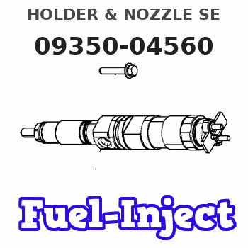
Information holder & nozzle se
Rating:
Compare Prices: .
As an associate, we earn commssions on qualifying purchases through the links below

4X Fuel Injector ME016991 093500-4560 0935004560 for Mitsubishi 4D
TUWODE Part Number: ME016991 093500-4560 || Item Type: Fuel Injector || Applicable Models: Fit for Mitsubishi 4D || Well-functioning fuel injectors ensure the correct air-fuel ratio, which is essential for minimizing harmful emissions. || Fuel is broken into fine droplets for optimal air mixing and enhanced combustion efficiency.
TUWODE Part Number: ME016991 093500-4560 || Item Type: Fuel Injector || Applicable Models: Fit for Mitsubishi 4D || Well-functioning fuel injectors ensure the correct air-fuel ratio, which is essential for minimizing harmful emissions. || Fuel is broken into fine droplets for optimal air mixing and enhanced combustion efficiency.
Components :
| 001. | HOLDER & NOZZLE SE | 09350-04560 |
Scheme ###:
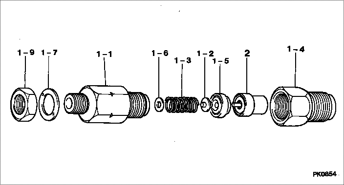
| 000. | [01] | 09350-04560 | HOLDER & NOZZLE SE | ME016991 |
| 001. | [01] | 09310-04560 | HOLDER ASSY, NOZZL | ME728159 |
| 001-001. | [01] | 09311-04560 | BODY SUB-ASSY, NOZ | ME728589 |
| 001-002. | [01] | 09312-10030 | PIN, NOZZLE HOLDER | MM500135 |
| 001-003. | [01] | 09312-70020 | SPRING, NOZZLE HOL | ME022313 |
| 001-004. | [01] | 09316-41370 | NUT, NOZZLE RETAIN | ME728590 |
| 001-005. | [01] | 09317-40011 | DISTANCE PIECE | ME703620 |
| 001-006. | [1C] | 09317-50120 | WASHER | MM500776 |
| 001-006. | [1C] | 09317-50130 | WASHER | MM500777 |
| 001-006. | [1C] | 09317-50140 | WASHER | MM500778 |
| 001-006. | [1C] | 09317-50150 | WASHER | MM500779 |
| 001-006. | [1C] | 09317-50160 | WASHER | MM500780 |
| 001-006. | [1C] | 09317-50170 | WASHER | MM500781 |
| 001-006. | [1C] | 09317-50180 | WASHER | MM500782 |
| 001-006. | [1C] | 09317-50190 | WASHER | MM500783 |
| 001-006. | [1C] | 09317-50200 | WASHER | MM500784 |
| 001-006. | [1C] | 09317-50110 | WASHER | MM500775 |
| 001-006. | [1C] | 09317-50100 | WASHER | MM500774 |
| 001-006. | [1C] | 09317-50010 | WASHER | MM500765 |
| 001-006. | [1C] | 09317-50020 | WASHER | MM500766 |
| 001-006. | [1C] | 09317-50030 | WASHER | MM500767 |
| 001-006. | [1C] | 09317-50040 | WASHER | MM500768 |
| 001-006. | [1C] | 09317-50050 | WASHER | MM500769 |
| 001-006. | [1C] | 09317-50060 | WASHER | MM500770 |
| 001-006. | [1C] | 09317-50070 | WASHER | MM500771 |
| 001-006. | [1C] | 09317-50080 | WASHER | MM500772 |
| 001-006. | [1C] | 09317-50090 | WASHER | MM500773 |
| 001-007. | [01] | 09324-50110 | WASHER | MM500139 |
| 001-009. | [01] | 94905-02480 | NUT, HEXAGON | MM500141 |
| 002. | [01] | 09340-01400 | NOZZLE ASSY | ME016527 |
Include in #3:
09350-04560
as HOLDER & NOZZLE SE
Include as Nozzle:
0930003380
as Nozzle
Cross reference number
| Part num | Firm num | Firm | Name |
| 09350-04560 | ME016991 | HOLDER & NOZZLE SE | |
| ME016991 | MITSUBISHI | HOLDER & NOZZLE SE |
Information:
Illustration 1 g00565418
4W-8471 Time Delay Relay
Use a 6V-7070 Digital Multimeter, a stopwatch, and a battery (8 volts to 40 volts) for this test.
Connect the positive lead of the voltage source to terminal (TD-4) of the time delay relay. Connect the negative lead to terminal (TD-3). If the test is done on an engine, the start/stop switch must be in the STOP position in order to power terminal (TD-6). All connections must be maintained until the tests are completed.
Use the multimeter to determine continuity. Compare the measurements to the following table.
Table 1
Terminals Relay Position
5-6 Closed
6-7 Open
Connect the positive lead of the voltage source to terminal (TD-1). If the time delay relay is tested on the engine do not leave the voltage source hooked to terminal (TD-1) for more than 60 seconds. The fuel shutoff solenoid will be energized. Use the multimeter to determine continuity. Compare the measurements to the following table.
Table 2
Terminals Relay Position
5-6 Open
6-7 Closed
Remove the positive lead of the voltage source from terminal (TD-1). Use the stopwatch to measure the time that is needed for the position of the relay to change. Use the multimeter to determine continuity. Compare the measurements to the following table.
Table 3
Terminals Delay Time of Relay Position
0 to 60 seconds 80 seconds or more
5-6 Open Closed
6-7 Closed Open Note: If a jumper is normally installed across terminals (TD-2) and (TD-3), the jumper must be removed before performing Step 5.
Connect the positive lead of the voltage source to terminal (TD-2). If the time delay relay is tested on the engine, do not leave the voltage source on terminal (TD-2) for more than 60 seconds. The fuel shutoff solenoid will be energized. Use the stopwatch to measure the time that is needed for the position of the relay to change. Use the multimeter to determine continuity. Compare the measurements to the following table.
Table 4
Terminals Delay Time of Relay Position
0 to 8 seconds 10 seconds or more
5-6 Closed Open
6-7 Open Closed
Remove the positive lead of the voltage source from terminal (TD-1). Use the stopwatch to measure the time that is needed for the position of the relay to change. Use the multimeter to determine continuity. Compare the measurements to the following table.
Table 5
Terminals Delay Time of Relay Position
0 to 60 seconds 80 seconds or more
5-6 Open Closed
6-7 Closed Open
Remove the voltage source from terminal (TD-4). Use the multimeter to determine continuity. Compare the measurements to the following table.
Table 6
Terminals Relay Position
5-6 Closed
6-7 Open