Information holder & nozzle se
Rating:
Compare Prices: .
As an associate, we earn commssions on qualifying purchases through the links below

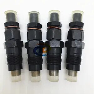
3X 0935004540 093500-4540 Fuel Injector Compatible with Kubota D1403/D1403B F2503TD
OfkZynodor Part Name:Fuel Injector || Part Number:0935004540 093500-4540 || Application: Compatible with Kubota D1403/D1403B F2503TD || Please make sure to carefully compare the photos and check the part numbers before making the purchase. If you are unable to confirm your engine model or part number, please leave us a message and we will assist you in confirming that the product you purchase is the one you need. || Your order is not merely a single purchase but the beginning of a cooperative journey, aiming to ensure the safe and smooth operation of your vehicle. We are proud to offer you reliable precision engineering components and unparalleled services.
OfkZynodor Part Name:Fuel Injector || Part Number:0935004540 093500-4540 || Application: Compatible with Kubota D1403/D1403B F2503TD || Please make sure to carefully compare the photos and check the part numbers before making the purchase. If you are unable to confirm your engine model or part number, please leave us a message and we will assist you in confirming that the product you purchase is the one you need. || Your order is not merely a single purchase but the beginning of a cooperative journey, aiming to ensure the safe and smooth operation of your vehicle. We are proud to offer you reliable precision engineering components and unparalleled services.
3X 0935004540 093500-4540 Fuel Injector Compatible with Kubota D1403/D1403B F2503TD
Yuubryczny 🚕Part Name:Fuel Injector || 🚕Part Number:0935004540 093500-4540 || 🚕Application: Compatible with Kubota D1403/D1403B F2503TD || 🚕Precise matching is the first step towards safe driving! To ensure that the accessories fit perfectly with your beloved car, please make sure to check the product details page before placing an order or contact us privately. Your meticulousness is the best guarantee for driving safety! || 🚕"Thank you for your trust and support! If you have any questions regarding the products, please feel free to contact us at any time. We will do our best to solve them for you. Wish you a pleasant experience!"
Yuubryczny 🚕Part Name:Fuel Injector || 🚕Part Number:0935004540 093500-4540 || 🚕Application: Compatible with Kubota D1403/D1403B F2503TD || 🚕Precise matching is the first step towards safe driving! To ensure that the accessories fit perfectly with your beloved car, please make sure to check the product details page before placing an order or contact us privately. Your meticulousness is the best guarantee for driving safety! || 🚕"Thank you for your trust and support! If you have any questions regarding the products, please feel free to contact us at any time. We will do our best to solve them for you. Wish you a pleasant experience!"

shsiyayh 1X Fuel Injector for Kubota D1403/D1403B F2503TD 093500-4540 0935004540
shsiyayh Part Name:Fuel Injector || Part Number:093500-4540 0935004540 || APPlication: Compatible with Kubota D1403/D1403B F2503TD || 1.Please tell us of your engine model or a view of nameplate when order this item to lower the error rate.Thanks. || 2.There are no instructions included in this kit.it is recommended to install professionally.
shsiyayh Part Name:Fuel Injector || Part Number:093500-4540 0935004540 || APPlication: Compatible with Kubota D1403/D1403B F2503TD || 1.Please tell us of your engine model or a view of nameplate when order this item to lower the error rate.Thanks. || 2.There are no instructions included in this kit.it is recommended to install professionally.
You can express buy:
USD 71.72
13-05-2025
13-05-2025
4pcs 093500-4540 16082-53001 093400-5800 DN0PD80 Fuel Injector For Kubota D1403/D1403B F2503TD
USD 45
13-05-2025
13-05-2025
4PCS Injector Nozzle DN0PD80 093500-4540 093400-5800 For Kubota D1403 D1503 D1703 V2003 V2203
Components :
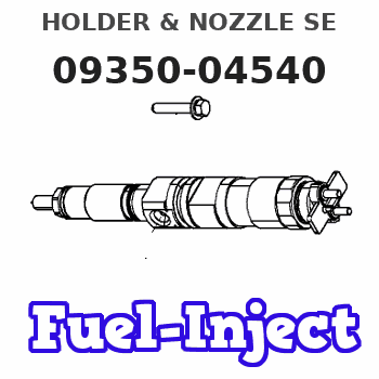
| 001. | HOLDER & NOZZLE SE | 09350-04540 |
Scheme ###:
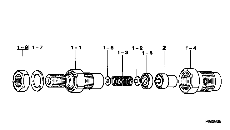
| 000. | [01] | 09350-04540 | HOLDER & NOZZLE SE | 16082-53001 |
| 001. | [01] | 09310-04540 | HOLDER ASSY, NOZZL | 16082-53011 |
| 001-001. | [01] | 09311-04540 | BODY SUB-ASSY, NOZ | |
| 001-002. | [01] | 09312-10380 | PIN, NOZZLE HOLDER | |
| 001-003. | [01] | 09312-70370 | SPRING, NOZZLE HOL | |
| 001-004. | [01] | 09316-41351 | NUT, NOZZLE RETAIN | 16475-53281 |
| 001-004. | [01] | 09316-40950 | NUT, NOZZLE RETAIN | 15841-53281 |
| 001-005. | [01] | 09317-40070 | DISTANCE PIECE | |
| 001-006. | [1C] | 09317-51980 | WASHER | |
| 001-006. | [1C] | 09317-51970 | WASHER | |
| 001-006. | [1C] | 09317-51960 | WASHER | |
| 001-006. | [1C] | 09317-51950 | WASHER | |
| 001-006. | [1C] | 09317-51940 | WASHER | |
| 001-006. | [1C] | 09317-51930 | WASHER | |
| 001-006. | [1C] | 09317-51920 | WASHER | |
| 001-006. | [1C] | 09317-51910 | WASHER | |
| 001-006. | [1C] | 09317-51900 | WASHER | |
| 001-006. | [1C] | 09317-51990 | WASHER | |
| 001-006. | [1C] | 09317-52000 | WASHER | |
| 001-006. | [1C] | 09317-52090 | WASHER | |
| 001-006. | [1C] | 09317-52080 | WASHER | |
| 001-006. | [1C] | 09317-52070 | WASHER | |
| 001-006. | [1C] | 09317-52060 | WASHER | |
| 001-006. | [1C] | 09317-52050 | WASHER | |
| 001-006. | [1C] | 09317-52040 | WASHER | |
| 001-006. | [1C] | 09317-52030 | WASHER | |
| 001-006. | [1C] | 09317-52020 | WASHER | |
| 001-006. | [1C] | 09317-52010 | WASHER | |
| 001-006. | [1C] | 09317-51890 | WASHER | |
| 001-006. | [1C] | 09317-51880 | WASHER | |
| 001-006. | [1C] | 09317-51870 | WASHER | |
| 001-006. | [1C] | 09317-51750 | WASHER | |
| 001-006. | [1C] | 09317-51740 | WASHER | |
| 001-006. | [1C] | 09317-51730 | WASHER | |
| 001-006. | [1C] | 09317-51720 | WASHER | |
| 001-006. | [1C] | 09317-51710 | WASHER | |
| 001-006. | [1C] | 09317-51700 | WASHER | |
| 001-006. | [1C] | 09317-51690 | WASHER | |
| 001-006. | [1C] | 09317-51680 | WASHER | |
| 001-006. | [1C] | 09317-51670 | WASHER | |
| 001-006. | [1C] | 09317-51760 | WASHER | |
| 001-006. | [1C] | 09317-51770 | WASHER | |
| 001-006. | [1C] | 09317-51860 | WASHER | |
| 001-006. | [1C] | 09317-51850 | WASHER | |
| 001-006. | [1C] | 09317-51840 | WASHER | |
| 001-006. | [1C] | 09317-51830 | WASHER | |
| 001-006. | [1C] | 09317-51820 | WASHER | |
| 001-006. | [1C] | 09317-51810 | WASHER | |
| 001-006. | [1C] | 09317-51800 | WASHER | |
| 001-006. | [1C] | 09317-51790 | WASHER | |
| 001-006. | [1C] | 09317-51780 | WASHER | |
| 001-007. | [01] | 09324-50140 | WASHER | |
| 001-009. | [01] | 94905-04260 | NUT, HEXAGON | |
| 002. | [01] | 09340-05800 | NOZZLE ASSY | 16082-53611 |
Include in #3:
09350-04540
as HOLDER & NOZZLE SE
Include as Nozzle:
Cross reference number
| Part num | Firm num | Firm | Name |
| 09350-04540 | 16082-5300 | HOLDER & NOZZLE SE | |
| 16082-53001 | KUBOTA | HOLDER & NOZZLE SE |
Information:
Illustration 1 g00564355
7W-2743 Electronic Speed Switch (ESS)
(1) Push button for Overspeed Verification
(2) Reset button
(3) Overspeed indicator lamp
(4) Seal screw plug for adjusting the engine overspeed
(5) Seal screw plug for adjusting the crank terminate speed
(6) Seal screw plug for adjusting the oil step pressure speed setting The calibration of the crank terminate adjustment can increase the crank terminate speed or the calibration of the crank terminate adjustment can decrease the crank terminate speed. The crank terminate speed determines when the starting motor is disengaged. The starting motor is disengaged when the system voltage is cancelled by the crank termination speed. At the crank terminate speed, the engine must be able to run without the assistance of the starting motor.
Remove the lockwire and the seal from seal screw plug (5). Remove seal screw plug (5) from the access hole for the crank terminate adjusting screw.
Use a small screwdriver to lightly turn the crank terminate adjusting screw in the direction of the "MAX" arrow or the clockwise direction. Turn the screw twenty times. The crank terminate adjusting screw will vary the setting of a potentiometer that is inside of the ESS. The crank terminate adjusting screw will not cause damage to the potentiometer. Also, the screw can not be removed if the screw is turned in the wrong direction.
Turn the crank terminate adjusting screw for twelve turns in the opposite direction of the "MAX" arrow or the counterclockwise direction. This will establish an approximate crank terminate setting.
Connect a voltmeter with the positive lead at terminal (ESS-12) and the negative lead at (ESS-5). Use a 6V-7070 Digital Multimeter or a voltmeter with the same accuracy. Start the engine. Record the engine rpm when the starting motor disengages. The starting motor disengages when the open circuit voltage is cancelled by the crank terminate setting. Refer to the Speed Specification Chart for the correct crank terminate setting.
If the setting in Step 4 is not correct, proceed with Steps 6, 7, and 8. If the setting is correct go to Step 8.
Stop the engine and turn the crank terminate adjusting screw for one full turn in the clockwise direction in order to increase the crank terminate speed. Turn the crank terminate adjusting screw for one full turn in the counterclockwise direction in order to decrease the crank terminate speed.
While the voltmeter is still connected, start the engine. Record the engine rpm when the starting motor disengages. The starting motor will disengage when the voltage is cancelled by the crank terminate speed. Repeat Steps 6 and 7 until the crank terminate speed is correct.
Install seal screw plug (5) in the access hole for the crank terminate adjusting screw. Tighten the screw to a torque of 0.20 0.03 N m (1.8 .3 lb in). Install the lockwire and the seal if the overspeed calibration and the oil step speed calibration are also complete.